Capture Output Data
The Capture Window shows, in real time, the data SigmaStudio is sending to the hardware. This includes data sent during compile/link/download, register read/write operations, and changes to schematic block controls. The following example provides an explanation of the data displayed in the capture window.
Output Capture Example :
This example uses the AD1940 DSP and the sample schematic shown below: utilizing a White-Noise Source, Medium Size EQ Filter (single precision), and Output block.
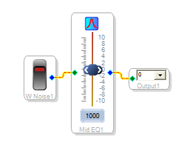
Display the Capture Window by selecting View - Capture Window in the application's main menu or by clicking the button on the Standard Toolbar.
Select the Schematic tab and compile/link/download the project. The compiled program data is downloaded to the hardware and displayed in the Capture Window.
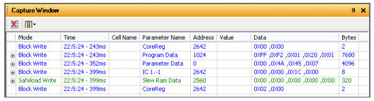
- For the AD1940, the first data sent is to mute the board. You can see that the parameter address for muting is 2642 and the values are 0x00 0x00.

- Next is the program code block, starting at address 1024, and utilizing 165 of the available 7680 byte program memory. Click the plus button in the left-hand column to expand this row and see all the data values.

- The following row is the parameter data, address 0, which is updated in real time as you can see once you make changes to sliders, control knobs, etc. on a compiled schematic.

- The next write message is across 5 registers, addresses 2642-2646 (8 total bytes), configuring the RAM, serial output, and Serial Inputs.

- This block of code is to configure the AD1940's slew ram, at address 2560. Note that this is shown if green because it is a Safeload write.

- The final row is the un-mute message. Observe that the address is again 2642, as with the mute command, but now the data values have changed to un-mute the hardware.

At this point you can click Clear All Output Data button to empty the capture window. Now try moving the EQ slider to see that as the values are changed they are sent to the DSP.
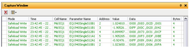
Cell Name - Same name as appears on the visual block in the SigmaStudio schematic tab.
Parameter Name - Describes the algorithm, IC type, number of inputs, and for this example the filter coefficient.
Parameter Address - The address where data are being sent.
Parameter Value - The decimal equivalent value for filter coefficient.
Parameter Data - 4-byte hex representation of the filter coefficient. The DSP takes data in 5.23 format, 5 bits to the left of the decimal point and 23 bits to the right. The hex values listed here are the 4 bytes necessary to store the 28 bits. Only 28 bits of the 32 available are used, so the 4 most significant bits of the first hex value are sign-extended from the 4th bit.