ADAU1701 Balanced output options
Hello there,
I am little confused about choosing the best option for balanced output stage from the ADAU1701 DSP.
I was thinking about 2 options, attached all of the them.
I would appreciate help from anyone who can advice witch method to choose, and best one to achieve the BALANCED output. and lowest noise ratio
Option 3 will perform as option 2 ?
My application requires 1 balanced output, and one unbalanced output, also attached option for that
Thanks for all
Audio Signal Processors
SigmaDSP Audio Processors
adau1701
Hi Microsim4,
In my experience I have always had noise problems using IC to get balanced outputs, so when I have this need I use a good translator sized according to needs, then ratio 1/1 1/2 etc.
The shield of the translator connected to the common gnd is then the maximum.
Above all, you can use only one DAC by connecting the primary winding of the translator between a DAC and gnd to have the balanced output on the secondary.
Are the DACs synchronized well enough to be a truly balanced output? I suspect that interchannel delays may be too high for that to work, but perhaps if you're at a high enough sample rate (or don't care about higher frequency noise) it could work acceptably.
I'm not crazy about any of those circuits, but if the DACs are synchronized well enough I'd just crib a circuit from one of Self's excellent books, such as Small Signal Audio Design, chapter 15.
Hello all,
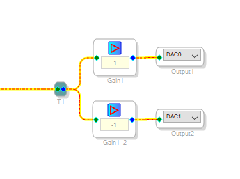
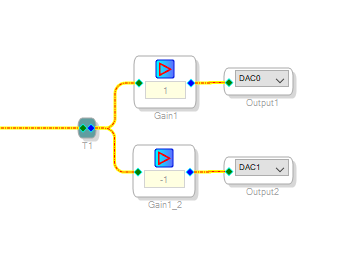
If you keep the paths identical, the outputs should sync:
However, as Piero pointed out, there's more to a truly balanced line output than simply providing two out-of-phase signals. A transformer-coupled balanced output actually allows the receiving device to establish its own ground reference, providing a signal path that's perfectly balanced for the lowest noise. It also uses only one DAC.
Interestingly, you don't need to use a physical transformer to get this level of performance. Analog Devices makes a chip specifically for driving balanced audio lines, the SSM2142. A cross-coupled feedback arrangement emulates the transformer effect. It works quite well.
To get your unbalanced output, tap the DAC output before the SSM2142, having it feed a single-ended op-amp or driver. Don't use one of the SSM2142's balanced outputs to derive a single-ended output -- the transformer effect renders such a connection ineffective.
Best regards,
Bob
I did not know SSM2142, because I never looked for an IC to balance an audio signal.
It 'a nice device but it needs and could not be otherwise, dual-type power supply.
This involves a more complex power supply and in any case the introduction of noise.
It always depends on what you want to get.
Surely the solution of the translator is more expensive and in my humble opinion, however, is the one that guarantees the best results.
Piero.
Hi Dave
I did not write anything about filtering on the DAC before it was connected to the transformer, for me it was implied.
You did well to report this particular.
Personally, when I used IC to obtain balanced linnees I have always had big problems,
I have always solved them with the classic translator, without complicating my life with double feeds, etc.
Surely the solution with the translator is more expensive, but the results in my humble opinion are higher.
The choices are always made according to the results that are to be obtained, but above all from the final cost of the object which will then have to be marketed.
Piero.
Hello Piero,
Your circuit #2 I would not do. The propagation delay between the two Op-Amps will cause some phase shift at higher frequencies.
I would worry about filtering the noise out of the DAC first. So connecting directly to a transformer is not a good idea. It is too much of a load for the DAC output. So I suggest filtering the output first. Then you will have an Op-Amp with decent drive capability.
Look at the AD1938 figure 31 or 32 on page 30 of the datasheet. The output circuit can be adjusted for your circuit requirements. The 3.3nf and 49K9 to ground are to filter RF from outside the unit and prevent the leakage of the 4.7uf cap from raising the output to a DC voltage. So these two components can be removed. Then the 604 ohm series resistance is also dependent of the application. If it is to drive a high capacitance line like a cable, then you need the higher resistance. It also protects against a short if someone cuts the wire etc. So if you use this circuit to drive a transformer then it can be a lower resistance or if you drive the SSM2142 then 47 ohms may be enough. The SSM2142 and similar parts like to be driven from a low impedance source. If you drive it directly from the DAC output then you might see some SNR degradation. You also want to filter out the out-of-band noise from the DAC. That is always a good idea.
Something else to look into is the SSM6322. It is a fairly new part and runs on a lower voltage but it still requires bi-polar supplies and I do not think one 5V supply could be used as a 2.5V +/- power supply since the minimum is typical supply is 3.3V bi-polar. I have not had a chance to experiment with this part to see what it can do. It was designed by another group here at ADI.
So I would look to use the circuit in the AD1938 and you could use two of them, one each for two DACs, then run those differentially into a transformer. That is also something to experiment with.
Regarding the questions about the two DAC being synchronized. The SigmDSP platform calculates the entire program every sample period and stuffs the data into the DSP output buffers. Then at the end of the sample period they all get transferred out to the DACs at the same time. There will be no difference in the output. The only way that could happen is if the two channels are processed differently inside the DSP. Like adding a delay to one and not the other. Or having one go through more filtering then the other channel. Then you will see the phase shift of the filter. So as long as you treat both signal paths the same then they will not be phase shifted. KJBob showed you how to invert one of the outputs to make it differential.
Well, that is my 2-cents on topic.
Dave T
Please log in to reply.