ADAU1452 Audio problem
Hello Team,
We are using ADAU1452 evaluation board.
While testing with evaluation board the whole thing was fine. We got output as per our requirement. And then we made a customized board with similar schematics.
Tested with simple audio program (i.e Playing square signal at output side). the circuit is not working fine. What may be the problem. Kindly help us to resolve the problem. We are using AD1938 audio codec.
Regards
Siva
Audio Signal Processors
adau1452
ad1938
adau1452 sigmastudio
Integrated/Special Purpose A/D Converters
SigmaDSP Audio Processors
Audio CODECs
Show More
Hello Siva,
Please include your hardware schematics, your SigmaStudio schematics and PCB layout details. There can be many reasons why it is not working.
Are you able to readback levels from the DSP? Do the meters work?
Dave T
Hello Dave,
Thanks for your reply. Kindly find the attachments of hardware and sigma-studio schematics
Regards
Siva

Hello Siva,
Let me make comments as I look at these pictures.
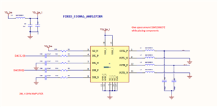
First, the codec. The ADC is differential. I would terminate the negative input with a cap to ground, 10uf is best but it could be smaller. It may not make too much of a difference but it may prevent issues in the future with RFI.
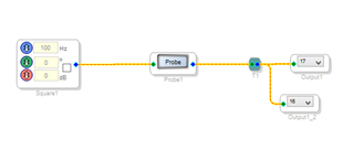
Your SigmaStudio schematic. Let me mention this just in case you missed it. Don't forget to actually turn on the oscillator. The checkbox is not checked in your screenshot so it will not be sending out anything.
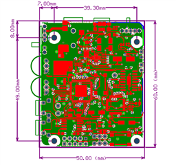
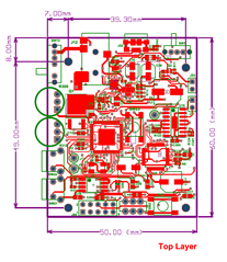
It looks like your layout is only two layers. You may be able to get it to work with only two layers but the audio performance will suffer and you may get some clicks and pops from errors in the digital transmission.
It also looks like the decoupling on the power and ground pins are not done well. It is difficult to do with two layers. You might not have properly connected the PLL loop filter components on the codec and that can cause issues with it starting up. It is difficult for me to see for certain from the small screenshot.
So first, why don't we determine if the DSP is up and running.
Check that it has power. AVDD, DVDD, and IOVDD. Make sure they are clean and the correct voltage.
Check that the Master Clock signal is correct, I will assume 12.288MHZ and it looks good on a scope.
Next to follow your tests of just the output from the DSP.
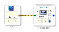
Modify your SigmaStudio program to have a Readback and a DC cell so you can see if you are properly communicating with the DSP and it is loading the program. It should be setup like the picture below:
If you are reading a "1" then you are communicating.
You can also place a meter in your project and a volume control to see some signals and that it is alive.
Check the I2S signals coming from the DSP going over to the codec. The LRCLK and BCLK have to come from the DSP since the Codec is configured as a slave. See on a scope if you are getting data from the DSP.
Then check that it is actually getting to the correct codec pins.
Then check that the codec is getting master clock. Again, look at it on a scope.
Check that the ADC data is being transmitted. then see if it is getting to the DSP and that it is getting into the core.
So with all this it will give you an idea of the overall health of the system and hopefully you will find some anomaly that can be chased to find the source of the problem.
Dave T
Oh,! One more small thing.
I would not recommend that you drive a diode directly from the DAC output. I would go through a transistor. I have done this before and was able to vary the brightness using the DAC. But it is too much current for the DAC to directly source or sink.
Dave T
Hello Dave,
Thanks for your detailed reply.
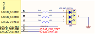
I have another query, how to interface RGB led with adau1452 to know the battery status (i.e) Battery low, Battery charging, Battery charged. And i have inserted LED schematics.
Regards
Siva
Hello Siva,
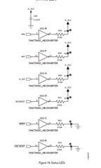
On our ADAU1452 eval boards we are using a hex inverter to drive the LEDs off of a GPIO.
You can see it on page 23 of user guide UG-636
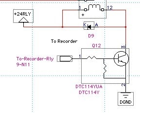
Another way it can be done is to use a pre-biased transistor. These are great in that you do not need any resistors to drive a relay and for an LED all you will need is the current limiting resistor in series with the LED. Here is a picture of it being used to drive a relay.
I used a DTC114YUA but there are others available. Search for "pre biased transistor" on your parts distributor's web site and you should find lots of options. They are really small and low cost. You can drive the transistor right off of the GPIO pin. No need for any resistors.
So how are you sensing the battery charging and low battery etc.? Do you have an external controller or do you want the DSP to do this? Have you worked out those details?
Dave T
Hello Dave,
Thanks for your reply.
The sensing is done by using MCP73830 Battery management IC. I want DSP to do battery monitoring (i.e) Status of the battery using RGB LED to indicate battery low battery charged and battery charging.
Regards
Siva
Please log in to reply.