ADAU1442 output port corruption with unassociated async input clocks
Hi, we are having an issue noted with ADAU1442 SigmaDSP on a custom PCB that may point to possibility of a silicon bug on the DSP. This project has had >1kpcs made over the past four years and behaviour is consistent across them.
Brief hardware description:
6-layer PCB with continuous power & ground planes and extensive decoupling. DSP has its 1.8V core voltage generated with a switching regulator and shares it with an ARM CPU & DDR memory, as well as the 3.3V switching regulator. An AD FAE upon initial request of a prior question reviewed schematics and layout and did not find anything amiss.
DSP is clocked with a 12.288MHz oscillator, fs fixed to 48kHz, DSP's Buffered Oscillator clock output then drives via fanout buffers MCK of the attached I2S codecs and an S/PDIF transmitter.
For all tests the controller CPU was held in reset and the DSP programmed with a minimalist program via SigmaStudio.
PROBLEM: periodic corrupted data on output ports when serial output port 1 is clocked from asynchronous clocks on clock domain 6
- The DSP's serial output ports 1 and 2 are connected to an asynchronous load as 2x TDM8 outputs (so 16ch output total). This is slave-clocked by the load chip to the DSP's clock domain 6, and then synchronized to the local clock via the 16 ASRC channels of the DSP.
- With the simplest possible SigmaStudio project where an internal DSP tone generator drives the I2S outputs of the DIT, there is no problem as long as serial output port 1 is NOT set to be clocked from clock domain 6, or if these clocks are physically disconnected.
- The moment that one of these are connected, the S/PDIF receiver (any external DAC with several being tried) produces periodic artefacts in series of two distortions 250ms apart, every 3.56s. These artefacts are related to the source signal frequency and amplitude and easily measurable and audible.
- Changing the DIT to a different manufacturer had the same result, and since the amplitude of the test tone affect the behaviour it appears to originates from the DSP.
- Changing the DIT's clock direction from slave to master (i.e. for the DIT to send LRCK & BCK back to the DSP) made no difference.
- Changing the DSP's MCK output to the DIT to to 512x fs_normal to double it to 24.576MHz made no difference.
- Digital waveforms look fine on an oscilloscope and measurements are extremely good on the analog domain when it's working so I doubt signal integrity or power supply issues.
- There is no issue when serial output port2, or any other unused serial output port, is set to be clocked from the async clocks on clock domain 6, ONLY serial output port1 which does not have any special significance. This happens despite port1 not being connected in the DSP project to anything, including ASRC's.
- When the TDM connections are actually being used, they themselves work fine(!)
- DIT is connected to DSP serial output port 5 as slave to the DSP. The same behaviour is found when connecting it to serial output 4 (and presumably others too although not tested).
- It should be noted that an I2S DAC connected to the same I2S clock domain and serial output ports (4 and 5) do not suffer from this and the measured analog performance in this case is fine. This may be though that the DAC's filter responds differently to whatever momentary I2S corruption occurs vs. the handling of the S/PDIF receiver when recovering the corrupted signal.
- Other clock domains than clock domain 6 were not tested for practical reasons but would be interesting to note whether moving the async clocks to other domains would shift the affected serial output port as well.
In summary, asynchronous clocks on clock domain 6 just seems to corrupt all the other serial data outputs if serial output port1 is set to be clocked by it, and whatever it does seems to affect S/PDIF transmitters but not DAC's.
Unfortunately testing this is not trivial due to the extremely long periods between the distortions since one would have to buffer all the samples over the entire 3.56s period which would require a specialist logic analyzer or large FPGA.
I can upload a simplified schematic but I trust the description is clear.
Audio Signal Processors
adau1442
SigmaDSP Audio Processors
Hello WattsAUD, Can you upload the minimalist program you were using. I would like to see the setup and try to replicate this on the bench. You will have to Zip the file for the file upload feature to work on the forum.
Dave T
Hello WattsAUD,
I reading this again, I am a bit confused as to what you are actually doing.
WattsAUD said:
With the simplest possible SigmaStudio project where an internal DSP tone generator drives the I2S outputs of the DIT, there is no problem as long as serial output port 1 is NOT set to be clocked from clock domain 6, or if these clocks are physically disconnected.
- The moment that one of these are connected, the S/PDIF receiver
You said "the moment on of these are connected to the SPDIF", What do you mean by "one of these"?
Reading further I am confused as to what is hooked up to what and what you are monitoring and what is being distorted. You say the TDM is fine , which uses Output 1, but then you say that Output one is corrupted. When you say the SPDIF transmitter, I am assuming you are talking about the SPDIF transmitter built into the SigmaDSP but re-reading I think this is an external SPDIF transmitter. A block diagram would be helpful for how you want me to hook this up and supply the project with the settings that reporduce the problem.
Thanks,
Dave T
Hello Dave,
Thanks for the response. I will prepare some diagrams etc. and upload sometime this week, but some quick comments below:
1) "one of those" means that the problem is not prevalent when either the async clocks are removed, or if the output port is set not to be clocked from it.
2) Distortion is measured in the analog domain of any DAC that is fed from a I2S DIT connected to the DSP's serial output 5 (DSP's internal DIT is not affected). It must be a DIT, not a DAC since as mentioned a DAC behaves fine under identical circumstances.
3) I did not say that Output 1 is corrupted. Clocking output 1 from async clock domain 6 causes the OTHER outputs to be corrupted. I did not check all the others, but at least output 4 and 5 are confirmed identically affected.
4) For the sake of simplicity, ignore the TDM connections as they play no role except that to note that they work fine. It is only their asynchronous clocks that seem to affect the other unrelated connections so if using the EVM you just need the following to reproduce:
- external I2S DIT on serial output port 5 (I tried both DIT4192 and AK4130A)
- asynchronous external TDM8 LRCK & BCK connected to clock domain 6
- external DAC
- active speaker and/or scope on DAC's analog output (either channel)
- tonegen in the DSP to drive the DIT. High frequency works best since it will not mask the artifacts and can easily be notched out, and high amplitude helps since the artifacts are related to source amplitude.
- DSP configured as mentioned with output port1 clocked from clock domain 6.
More details shall to follow shortly.
Hello Dave,
Below are two diagrams to assist with replicating the issue:
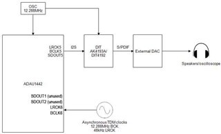
First is the connection diagram which shows connecting a synchronous external DIT to SDOUT5 with DSP in master mode, and thus clock domain 5 producing BCK and LRCK to the DIT. The DIT has the same 12.288MHz MCK as the DSP.
Connected to clock domain 6 are two asynchronous clocks as shown. They are used by SDOUT1 and SDOUT2, but for replicating the issue SDOUT1 and SDOUT2 need not be connected to anything.
The DIT feeds an external DAC and the output of the DAC is either monitored by ear or on a scope.
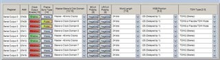
Below is the serial output setup. The only connection of importance is serial output 1, serial output 2 and serial output 5. Serial output 5 is master and is the output to the DIT. Serial output 1 and serial output 2 are the two TDM outputs that are clocked from the asynchronous TDM input clocks.
In the DSP project, set up a tonegen to drive the DIT of full amplitude and >10kHz, then monitor the DAC output. With this setup, one should note a repetitive set of pulses in sets of two, 250ms apart and the sets 3.56s apart. This will disappear if the TDM clocks are removed, or if serial output 1 is set to be slaved from a different clock domain.
Please log in to reply.