ADAU1467 - CORE_STATUS = 0
I recently received our new digital audio board which is equipped with an ADAU1467. We have an external master clock signal running at 24.576MHz, 3.9V pk-pk. Verified that we have the master clock on pin 25. PLL_CTRL1 is set to 8.
I use SigmaStudio 4.2 to download a simple program (just input from port 0 and output on ch 0 and 1) to the chip but something is not correct:
Core Control window says that PLL has locked, but N and M values are 0 for CLK GEN 1 and 2. If I change the values and read them back from the DSP I get back only 0.
I can't change CLKOUT, always 0. On the EVAL board it was possible to turn CLKOUT on/off on the pin by restarting PLL_ENABLE.
Moreover, CORE_STATUS is 0.
I have checked all voltages, and RESET is high when the DSP is supposed to be running.
Does anyone have a suggestion for what might be wrong or what I should check?!
/AJ
Audio Signal Processors
adau1467
core_status
SigmaDSP Audio Processors
Hello AJ,
I think you are not actually communicating with the part. Are you using SPI? That would be my guess.
If so then look carefully at the SPI connections and look at the data transfers to see if all the signals are correct. At first I thought you were trying to change the CLKOUT pin while the PLL was running but you were able to do it correctly on the eval board. That register is not able to be changed when the PLL is locked and running. It is a hardware lockout.
I suggest you try to read a register that is not a zero after reset. Like the PLL_CTRL0 register. It is an 0x0060 after reset. Do not try to program it so that you do not write over it. Until you can read this register correctly, there is no point moving forward to try to program it.
Check other things about the part.
Make sure the DVDD is correct.
Make sure the reset line is not being held low.
Make sure the PLL is locking. If it is not then the PLL loop filter should be checked.
Also, check the Selfboot pin. Make sure it is not set to selfboot. That would throw a wrench into your efforts.
Dave T
I'm actually using USBi and i2c thank's to your explanation. I have a logic analyzed spying on the traffic and can see that the dsp is sending ACKnowledgements upon read and write requests.
PLL_CTRL0 = 0x03! How is that possible? I have successfully changed reg 0xF000 to 0x60 by writing, then restarting the PLL. When I now perform a new clean download of the (still simple) project it remains at it's supposed default value of 0x60. However if I reset power to the whole board, then 0xF000 goes back to 0x03 (after new download from SigmaStudio). BTW, I can change the value of PLL_CTRL1 (since I'm running with clock 24MHz). But CLK_GENx N and M values still remain at 0 after write (for example _GEN1 M=6 and N=1) and PLL reset - that's definitively bad behavior. As before, CLOCK_STATUS = 0.
I have checked every write request during download and noticed some peculiarities:
* There are i2c errors when trying to write to F003 and F005 at the beginning of the download sequence, see fig
. at -1.5 ms (relative) there are missing SCL clock cycles so the data value has been corrupted. Then at -1ms, and at +1ms there are too many clock cycles at the end (The image does not show the error messages due to resolution). Definitely something to dig into.
* Also noticed that the i2c programming sequence does not include F8999 writes that are performed at the beginning when using spi as protocol. How come?
DVDD =1.21V
RESET is high.
PLL_LOCK = 0x01. However, I do not really trust that value.
Selfboot pin connected to gnd.

Have fixed all protocol errors during download, primarily by twisting and decreasing the length of the cables . Still core_status zero. I can change some few register as described earlier, but most of them remain 0. Same thing with PLL_CTRL0 which returns 0x0003 upon restart of the board. I even added write to _CTRL0 at the beginning of the download process and now always have the correct value of this register (0x0060). Still core_status = 0. Downloaded the same program to the EVAL board using i2c. Works as charm. All register values as expected. core_status = 0x0003 (sleep)
Conclusion:
The dsp chip is probably damaged.
Hello alexjaw69,
It is interesting that you keep getting 0x0030 for the PLL Control_0 register. It is like one bit is shifted. This may be a timing thing with the transfer. The fact that you made progress by twisting the cables is a good symptom. Are you running a ground wore along with the SDA and SCL wires? You should do that and twist them together or run them using a ribbon cable with ground on every other wire. Is your PCB a 4 layer or greater board with power and ground planes?
Another thing you can try is to slow down the I2C speed. Bring it down to 100kHz or lower. If you are running at 400kHz then the value of the pull up resistor will need to be smaller to speed up the edges.
Another subject, if you could upload the pictures to this forum rather than an outside server that would be good.
Thanks,
Dave T
Was also considering the shift. However, normal programming does not involve writing to F0000. When I include it in the programming sequence it becomes the correct value 0x0060.
Why is it possible for me to write to some registers? And why are most of the regs unchanged by write requests and remain 0? It's not that we sometimes are successful and sometimes not, i.e. not an intermittent issue. It seems that some parts of the chip are functioning while other parts are not. I have even, attached a 12.8MHz crystal and switched to the internal PLL. Still same behavior.
Yes, we have more than 4 planes.
Will check with 100kHz.
Thank's for support!
Hello Alexjaw69,
It still worries me that you have to set register F000 to 0x0060. It make me think that you are really setting it to 0x00C0. ( 0x0060 shifted over by one ). The fact that you read a 0x0030 is not a good sign.
I just tried an experiment with an eval board. I setup the sequencer to do a read of F000. Then I powered down the part and then read the register and it came back as 0x0060 as the datasheet says it should. This is with no program running and nothing was sent to the part at all.
Which registers are you trying to write to that remain 0?
How confident are you that the part is properly soldered down?
Did you include a SigmaStudio USBi header in your design?
If not then you still can cobble together a way to do that it would be good. Then you can use SigmaStudio to look into the part. You can also program your board from SigmaStudio to help verify the design.
Dave T
I'm using SigmaStudio and USBi, but communicate with i2c by using the appropriate pins (1,3,10) from the USBi cabble.
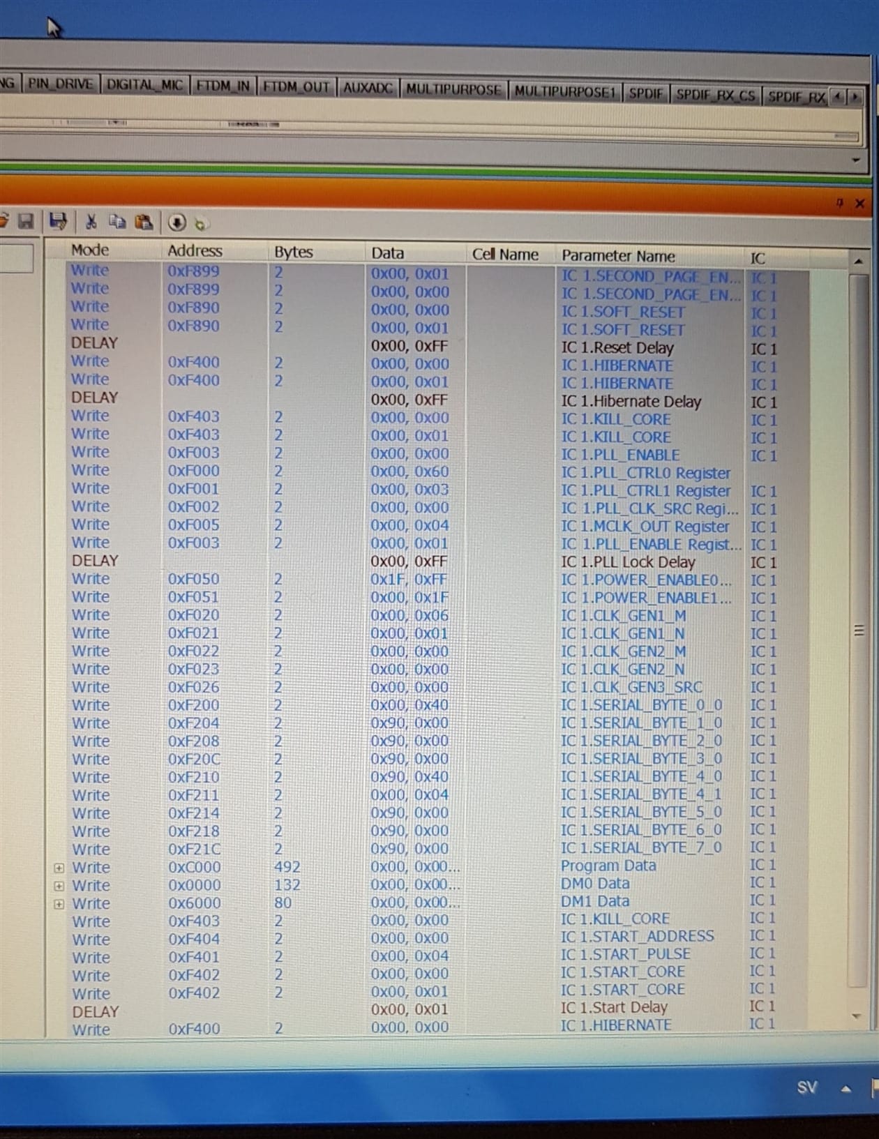
Observe that I read F000 = 0003 at power up. But if I write 0060 I also get back 0060. However, on reset it reverts to 0003. That's why I included a write to F000 to the programming sequence, which I still perform through SigmaStudio. I also tried to set M and N for clock gen 1. However, as most of the registers, I can't change it's value from 0. Other regs I notices that I can't change are the serial input and output registers. Also was curious about the power regs F050 and F051. Programming sequence sets these to 1FFF and 00FF, respectively. But when I read these out I get 0 for both!
Eventually I will read out all register values and compare. I wonder what is retained in the Program and DMx regs? However, I still consider that the fact that core_status = 0 indicates that something is seriously wrong and there are not so many thing that can be done wrong software wise in the beginning of the programming sequence (between PLL enable 0 and enable 1.)
I assume the soldering is done properly by our board supplier. However, I will ask them to put on a new chip in order to check if I get the same behavior.
Here is a zipped file with dsp project and two text files:
Project file. Same (funny... behavior) dsp but running with it's own osc as on the EVAL board. In this way I have been able to program my dsp and the EVAL board dsp with the same code and using i2c (SigmaStudio + USBi). Project does not contain anything else than USBi + the dsp. In this project I do not try to write a correct value to F000, i.e. this is pretty much bare bone init of 1467.
Text file 1. Read result of all control regs F000-FBFF. Reading performed with the sequence tool in SS, i.e. read (FBFF-F000+1)*2 bytes starting at F000.
2. Same read but from EVAL dsp processor programmed with the same project.
I ran a diff on the files and can conclude that the dsp on my board have values in the first 8 regs, everything else is 0! In these first 8 regs, all values are the same (for example PLL_LOCK bit is 1) besides F000 which is 0003, instead of 0060.
Hope that this can shed some light on what is happening with the chip.
hifibox_proto_4_12Mhz_IC 1.zip
Also included chip ID if that is of any interest.
x-ray image of the dsp chip
DSP.tif

The chip was probably damaged.
Have received a new board and now the dsp behavas as expected. This is the first prototype and we have some issues on the power part of the board. We have added some patches that we didn't had when we powered up the first board and we believe that it stressed the DSP.
Thanks again for your support,
AJ.
Hello Alexjax69,
Are you still having this issue or is this the result of the damaged part you described in your other post?
Dave T
No. The problem was configuration of register PLL_CLK_SRC which we had configured as XTALIN/MCLK. It seemed correct since we supplied an external clock signal on the corresponding pin (f=24.576MHZ). Now, when we have changed to "PLL CLOCK" and everything works as expected.
Hello alexjaw69,
Sorry you fell into a trap of a poorly named register. It really should be called the Core_CLK_SRC.
There is no choice of what feeds the PLL, it is always the XTALIN/MCLK pin but you can bypass the PLL and feed the core directly with the MCLK. This happens automatically when the part is powering up and before the PLL has locked, but then this register takes control after the program boots up. So you were running with a core rate of 24MHz which is super slow! Very few MIPS.
Glad you were able to figure it out. Sorry I did not catch this sooner.
Dave T
Please log in to reply.