Can't make Index Selectable Multiplexer work!
I know I'm neglecting something silly, but I just can't make one of these infernal devices switch. I need to select between two DC levels with a logic 1 or 0. I've used ABCD blocks before with no problem, but figured this time I'd just use the Index Selectable Mutliplexer. Here's my 'prove it doesn't work' circuit under two conditions:
In the top picture, the left ReadBack is showing a DC level of 1 and, sure enough, the full output of the DC Input Entry is switched through to the meter and the other ReadBack. But then when I Mute the control lead, and the switching level ReadBack shows a zero, the switch should go to the other input and drop the level 20dB. But it doesn't. I've also tried by replacing the Mute module with a second DC Entry, programming it for a zero or a one, and still can't make it switch. What am I doing wrong? I read the Wiki for that Multiplexer, but it doesn't specify logic levels, etc. Help!
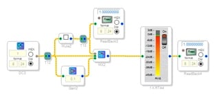
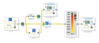
Well, a bit more reading suggests that a Lookup Table (LUT) needs to be part of this. So I dragged one onto the sheet and connected it to feed the control pin on the Multiplexer, but how to specify the value so that a 1 or 0 going in translates to the proper 'command' going out is over my head. I was able to switch between one input and something strange (pegged meter, oscillating ReadBack values), so I think I'll stick with the ol' ABCD module. Would be nice to know how to use the LUT, however.
Which processor are you using? I have some example programs but they differ greatly between DSPs.
Dave T
Great, Dave, thanks for the quick and welcome reply. It's the ADAU1451, which I'm running under Sigma 4.1. I'd love to have a better understanding of the whole Format business if there's a tutorial somewhere.
My need is for a simple SPDT 'relay' that can switch either audio or full-range DC control levels. It would be nice to switch back and forth with a 'DC' control input of zero and '1,' although 'other than zero' would be just as good as a '1.' But I'm not sure whether it's better to use the Index Selectable Multiplexer and the extra effort to translate to its logic input, or to continue to use the ABCD block, which works flawlessly. Whichever reduces to the simpler code and/or uses less overhead would be preferable.
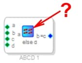
Speaking of the ABCD block, there are evidently five conditions, but only four are listed in the F1 or Wiki. From the low-res symbol for the fifth, I assume it's "Approximately Equal To," or maybe not:
Can you confirm?
Many thanks!
Hello Jim,
I have attached a project showing how to control a MUX switch using GPIO on a 1452 family of parts.
Here is a screenshot of the relevant part of the schematic.
The symbol on the ABCD cell is the "Equal To" symbol. The symbol needs to be an equal sign rather than an assignment sign in C language. "==".
Let me know if you need anything else.
Dave T
ADAU1452 GPIO Controlled Mux.zip
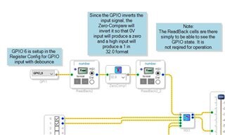
Many thanks, Dave; you're a veritable treasure trove of info. I'm going to give that a try this morning. My application switches from 'inside Sigma,' but I'm assuming that an internal '1' or '0' can do whatever the GPIO input is doing. The most informative thing here is using that ZeroComp as a level translator, assuming that it will take a '0' and most anything else in and output a properly-bit-assigned '0' or '1' to the Multiplexer. I suppose the Buffer Gate in that same branch of the tool tree could do the same thing without inversion.
Please log in to reply.