ADAU1467 Is there any shut down sequence?
Hi,
I'd like to know a requirement for shutdown sequence of ADAU1467.
There is not specifically mentioned in the datasheet.
Is there any problem even if shutting down without particular attention?
Thanks and Regards,
Audio Signal Processors
adau1467
SigmaDSP Audio Processors
SigmaDSP
Hi. No, there is no particular shutdown sequence required for the ADAU1467 since it does not have any on-board nonvolatile memory. If you are controlling it with a micro-controller, I would suggest ramping the outputs to 0 to avoid clicks, but nothing special is required.
Hi, Ken
I'd like to confirm one more.
Is there a specification (Voltage threshold level, hold time, etc.) for "Brownout"?
Best regerds, TomY
Hello TomY,
There is no brownout sensing circuit so that really needs to be done externally. It is the best place to do it anyway. The minimum voltages are listed in the datasheet in Table 3.
The best recommendation is to use a reset generator like we did on the evaluation board. Then if the sense voltage input is setup to be monitoring a voltage that would fall before the power supply caps for the DSP, then the reset generator will place the part in reset should there be a brownout before the voltage to the DSP would drop too low. There are also ways to use the Power-Good signals from a regulator. Another option is for the system controller to monitor the voltage and if the Power-Good goes away then reset the system.
This can be a longer discussion but it is a system design issue.
Dave T
Hi Dave,
I confirmed the minimum voltage in Figure 3.
Would you recommend a circuit that issues a system reset if it falls below the minimum voltage?
Practically, what voltage is appropriate?
Thanks and Regards,
Hello Takumi3952,
In our evaluation boards we use the ADM811TARTZ for a reset generator and monitor. It is available at several different trip voltages and the one we use trips at 3.08V. Th next lowest available voltage is below the min of 2.97V. It is 2.93V so it is slightly below. If your application might be running a little low you might choose this lower value.
I have attached the schematic of the EVAL-ADAU1452MINIZ. The user guide also has the bill of materials.
Dave T
EVAL-ADAU1452MINIZ_130520_2.pdf
Hi Dave,
Thanks, I'd like to continue the discussion little more.
When considering an in-vehicle system, the voltage may vibrate greatly in a short time.
In that case, I want to know if it needs to be restarted (reset) SigmaDSP if it is lower than the specific volts.
Is it 2.97V, isn't is ?
Thanks and Regards,
Hello takumi3952,
The system designers need to make efforts to stabilize the power to the unit. If the power fluctuates at a high rate then they will need to add more capacitance to the power to help smooth out those fluctuations before and after the regulators. We show a 10uf bulk cap on the IOVDD and AVDD but it might need to be greater. I would not increase the capacitance of the DVDD bulk cap if they are using the internal regulator. If it is an external regulator then they can study if it is possible to have more capacitance.
The AVDD is stated as 2.97V minimum but this only powers the analog sections of the part so that is the AUX ADCs. So short pulses will not cause problems.
The significant analog section of the part is the PLL. The PLLVDD has its own input pin so special attention can be afforded to that pin. It can have a ferrite bead and filter caps to clean up any noise on the AVDD power feed. There can be an extra bulk cap on that pin after the filter to help keep the power clean and stable. This will help prevent a PLL issue.
Then the IOVDD I assume is 3.3V in their system? Since the IOVDD can operate down to 1.71V this will help prevent issues caused by fast transients on the power line. Again, some extra bulk capacitance can be used here as well. The IOVDD does power the internal voltage regulator so since the IOVDD can operate as low as 1.71V, this means the internal regulator can properly supply the DVDD power when the IOVDD is as low as 1.71V. The DVDD is what powers the core and the memories etc. So if they are operating at 3.3V IOVDD then there is a lot of margin for the 3.3V power to dip before causing any issues.
I think having a reset generator set to 3.08V will reset the part well before the DVDD voltage will dip. Having good filtering and bulk caps on the incoming power will help prevent the fast transients that perhaps the reset generator might miss. Then anything faster will be filtered out by the time it goes through the DVDD regulator and its filters.
I would expect the automotive designers are very experienced in filtering the sometimes erratic power found in a vehicle. They can consider our bulk capacitance caps in the system diagrams to be the minimum required with the exception of the 10uf in the DVDD power after the internal regulator. That one needs to be a 10uf.
I hope this helps.
Dave T
Hi Dave,
Thanks for your reply.
I also assume that the customer's system is 3.3V.
What will happen if IOVDD changes from 3.3V to less than 1.71V?
Can I assume that the device is initialized?
In other words, Can I assume that POR works when the voltage dropped below this voltage again rises?
Thanks and Regards,
Hi Dave,
I'm always thankful for the strong support from you.
Customer's worry is to restart the DSP safely even when the voltage drops.
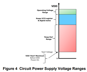
For example, please see Figure4 and 5 in the following document. Explanation of BoR is clearly stated.
www.analog.com/.../rf-pll-vco-power-up-brown-out-design-application-note.pdf
Customer wants to know the "Start voltage" mentioned here.
Is this voltage defined?
Thanks and Regards,
Hi Dave,
Thank you for always.
Based on the discussion so far, I understood as follows.
Brown-out-reset requires voltage management outside the DSP and it is designed to be reset on the evaluation board below 3.08V.
The lower limit value of PVDD of the device is 2.97V.
When it falls below this voltage, it can safely restart by resetting.
Please let me know if there is a mistake in my understanding.
Thanks and Regards,
Please log in to reply.