ADAU1467 DVDD regulator circuit
Hi, ADI support team
I found the following description in the ADAU1452 datasheet.
Is it applied to ADAU1467, too?
--------------------------------------------------
If a ceramic 10 μF capacitor is used, a 0.5 Ω series resistor must be added to compensate for the missing ESR of the electrolytic capacitor.
--------------------------------------------------
You recommend to add 0.5 ohm, but is it possible to show the safety value range of this series resistor?
Best regards, TomY
Audio Signal Processors
adau1452
adau1467
SigmaDSP Audio Processors
TomY.
Yes. This is a new recommendation that we are making for all of the ADAU145x and '6x parts now when using the internal voltage regulator to generate DVDD. We have never had a problem in practice, but simulations show that a small amount of damping here adds some extra margin of stability to the regulator.
The tolerance of this resistor is not critical at all just as the ESR on electrolytic caps can vary widely. We are not specifying a tolerance. Keep in mind that the 10μF cap is a bulk capacitor supplementing the 0.1μF bypass caps that should be very close to the IC across the DVDD and ground pins. Any abrupt change in the current demand on DVDD will mostly be met by the bypass caps. The resistor reduces any ringing that might bleed through to the voltage on the bulk cap.
Ken
Hi, Ken
Thank you for your answer.
I understood we don't need to care the tolerance of this 0.5 ohm resistor.
And then, please let me ask one more.
Is it possible to show a reasonability of 0.5 ohm value?
If possible, can you show it, like a following image?
Best regerds, TomY
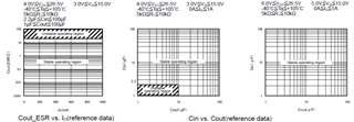
Hello TomY,
No, we do not have that kind of data. It is not very critical. It is there to replace the ESR of an electrolytic cap. When this regulator was designed, there did not exist low cost ceramic capacitors with around 10uf of capacitance. So the regulator was designed using an electrolytic cap. All electrolytic caps have high ESR when compared to a ceramic cap. So when we modeled the regulator using a ceramic cap the phase margin was lower than we would like to see. It was not in the unstable range.
So when you ask what the tolerance is, well the ESR tolerance of different brands and models of electrolytic caps varied widely! So some damping resistance is needed. The designer had mentioned less than an ohm and he used 0.5 ohms in his models and it looked good.
I should also mention that we have used ceramic caps on our eval boards for years without the resistor. There has been several manufacturers who have built products, including automotive products, that have not used the resistor and there have been no problems. In the lab I have tried to make the regulator unstable by putting on excessive capacitance and no resistance and was NOT successful in producing ANY instability. So this is simply a recommendation based on simulations and the idea that we want to be certain that it will be stable over all temperatures and skews and that we are doing our best to assure proper performance.
So certainly going to a more standard value like a 0.47 ohm resistor is fine.
Dave T
Hello, Dave
Thank you for your answer.
I will consider my design, based on your advice.
Best regards, TomY
Please log in to reply.