Questions: Design details of ADAU1701
Hello,
1. The EVAL board of ADAU1701 uses 10uF Tantalum capacitors for C24, C44 and C46. These are bulk capacitors for the different supply pins and I have no objection to the choice made.
I would, however, like to know if there would be a performance hit if Ceramic 10uF/X7R/0805 capacitor is used instead. This is asked purely from cost saving point of view.
2. Can I seal my custom board that uses ADAU1701 using epoxy/ potting compound? Will the design survive worst case operating temperatures of 50deg.C?
If it is ok to seal the board using epoxy compound, is there any recommended epoxy/ potting compound that I can use?
Thanks in advance!!
Audio Signal Processors
SigmaDSP Audio Processors
adau1701
Hello KKSL,
Not a problem using the ceramic parts. The Tantalum are used because when they were designed there were not many options for 10uf SMT caps other than electrolytic or tantalum. The schematic I am looking at has different cap reference designators. It is fine to just swap out the caps to ceramic on the CM pin, the FILTA and FILTD pins. The same for the IOVDD and AVDD pins.
For the DVDD pins it is a little different. If you are using the internal regulator with the external pass-transistor, you can change the 10uf cap to be ceramic but you need to add a small series resistor to the circuit. Around 0.5-ohms is good. Between 0.33 and 0.5 is fine. What it is needed for is to replace the ESR of an electrolytic cap which is much higher than a ceramic cap. The regulator was designed using an electrolytic cap and without it the phase margin of the regulator is less. It is not really bad but it is not optimal and so far we have not seen any issues with designs that did not have the resistor in series. I look at it as a preventative action in the design to make certain there will not be a problem with the regulator.
Your next question.... Potting compound? Wow, I have not had to deal with this since I left the military back in the dark ages. I had to learn to re-work boards that were potted. What fun! So I have not idea what compounds to use or not to use.
I am not a thermal expert but I will share my observations on this. I am sure you have seen the specs, the operating temperatures are up to 70deg. C. So it should be fine at 50deg C. What needs to be studied is the temperature of the junction when operating in high ambient temperature of the environment your product is in. How is heat dissipated from the PCB? If you look at the thermal resistance specification you see that the junction to ambient is very high. So it does not dissipate much of its heat via air transfer from the case. The thermal resistance to the case is much better so heat transfer to the PCB will be better. This datasheet was written before we specified the actual PCB details like number of layers and if it meets the JEDEC specs. So I suspect the potting will not cause much of a thermal issue as long as the heat from the PCB is dissipated and you use a couple of power planes in your PCB design. There are some good products now that are available to model the thermal properties of a PCB layout. You might want to do that if your project budget allows.
Dave T
Thank you for your early answer.
So, I'll go ahead and replace the 10uF tantalum with ceramic through out the board.
I will include a 0.47ohm/0.25W/3216 resistor in series with the 10uF cap on the DVDD pin as suggested by you.
I'll look into the potting compounds available and come back to you with its thermal properties, just to be sure. Maybe, at the end of the prototype test, I'll just put the potted board into a thermal chamber to determine its higher operating temperature limit.
Couple more things:
1. There is a 56nF cap on the PLL filter. The value is not very popular. Any suggestion to its replacement, if possible?
2. For 96k sampling, I have ADC_RES = 18k. The ADC input resistors are 8k (3.3k + 4.7k). I hope that this will give the correct scaling for the ADC full-scale resulting in optimum resolution.
Thanks!!
Hello KKSL,
1) The PLL filter is precisely calculated for the correct loop filter response. Changing it may affect the lock time, the ability to lock at extreme temperatures or the range of frequencies that it will lock to. It is also important for the rejection of jitter. When I have talked to the designers about this in the past they cringe and say No! cannot change it! So I will pass that on to you but caps are not exactly the most tight for tolerance. Here is what is in the datasheet on this subject:
The PLL loop filter should be connected to the PLL_LF pin. This filter, shown in Figure 15, includes three passive components—two capacitors and a resistor. The values of these components do not need to be exact; the tolerance can be up to 10% for the resistor and up to 20% for the capacitors.
So you should be able to slightly change the value but be careful. If you go to a new value make sure the tolerance of this part will not take the cap out of the range of the original 56nf +/- 20%. So you would have to go to a tighter tolerance.
2)
At 96kHz the ADC Resistor needs to be 8k. This value is calculated by the formula on page 20. Rt = 20k x 48k/fs with the Rt including the internal 2k of resistance. So ADC_RES + 2k = 10k, So ADC_RES = 8K.
Then on that same page is the formula for the input resistor. This will depend on what you want for a full scale rms input voltage.
Dave T
Hello again,
- The ADC_RES is corrected to 8.04k (4.02k + 4.02k). For Full scale input of 1.2V (+4dbu i.e 1.23V), the ADC input resistor is now 4.01k. I hope this should be fine now.
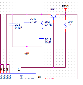
- The 0.47E/1%/0.25W/1206 representing ESR of the bulk capacitor on DVDD is connection as shown. I hope that it is as per what you meant.
Now for the output coupling capacitor:
The datasheet has a 47uF polar capacitor while the eval board has a 100uF polar cap that couples to a LPF of 50KHz.
I have two questions related to this:
1. Can this output coupling capacitor also be replaced by ceramic 10uF/X7R type?
2. The processor output connects to a power amplifier ( which is never used else where as standalone amp), which typically has a HPF with R = 22k and C = 1uF or 2.2uF film cap. Provided that it is ok to have a 10uF/X7R ceramic cap at the processor output, I want to get rid of the 1uF or 2.2uF film capacitor on the amplifier input. Do you see any issues with this?
Thanks!!
Hello KKSL,
You have the series 0.47, resistor to the 10uf cap in the right place.
The output coupling cap will depend on the input impedance of your amplifier and LPF. In our eval boards we have to allow for headphones to be directly connected to the outputs. The impedance can be quite low so we need to use a 100uf cap to keep from rolling off all the low end. We show a 47uf as a compromise in the datasheet to not scare away customers who will be driving an amp and do not want to have a large 47uf cap in their design.
So calculate the cutoff frequency of the 10uf cap driving into the input impedance of your amplifier. I suspect that it will be fine and will suit your needs.
What I don't know is how good these ceramic caps are for sound quality? I do not have golden ears.
It seems to me that you can get rid of the film caps. I could make the argument that you keep the film caps and use them instead of the 10uf. But I might not be seeing the complete picture of what you are doing. Film caps sound better and are more stable. The LPF will still work fine up at the common mode voltage of the DAC so the cap is not needed before the LPF, just do not use the 49.9K to ground as shown in the eval board schematic. That is only to keep the electrolytic leakage from rising up to a DC voltage when nothing is connected. Then plug in an amp and boom! Big pop from the DC.
Anyhow, that's my 2-cents on this topic.
Dave T
Hello Dave,
I have got rid of the 100uF caps on the processor outputs along with the 49.9k resistors and will retain the film caps on the amplifier inputs.
I like the cleaned up work and the BOM is much lighter now.
Thanks to you and regards!!
Hello again Dave,
I found this thread in connection with the ADC_RES: https://ez.analog.com/dsp/sigmadsp/f/q-a/66875/adau1701-adc-resistor-values-for-higher-sample-rates
For application running at 96K, and changing the ADC_RES to 8k, I got noise. On searching for some answers, I found the above thread.
Can you confirm as pointed by BrettG, that ADC_RES remains the same for 48K and 96K application?
Also, one user reported the that formula for input scaling resistors is also not correct. Could you also look into this and confirm the correctness?
Thanks!!
Hello KKSL,
I will look into this as best I can. At this point the part is getting older but I think some of the engineers are still around who worked on this project. It looks like Brett fell into the same trap as I did. He left ADI a long time ago and the SigmaDSP support went to a different person and he left so now I am supporting the SigmaDSP. There is a lot of learn about a lot of parts so I missed this detail. Seven years ago Brett would have had better resources to fall back on so I would take his info and run with it. I will ask around and reply back.
Dave T
Please log in to reply.