Reading ADC data in ADSP-21489 assembly
Hi,
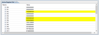
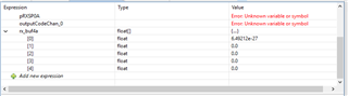
I have been reviewing and executing this code for several days and I don't understand why the value in R2 is correct, but the value in the rx_buf4a is very wrong. The value in R2 is coming from ADSP-21489 SPORT0 connected to an AD7768 converter. It contains 8-bit header and 24-bit data. (I am not using the interrupt, the code takes one reading)
Thanks
Dan
#include <def21489.h>
#include <sru.h>
/* Default Buffer Length */
#define BUFSIZE 10
.global sport0_isr;
.section/dm seg_dmda;
.var adc_hdr0;
.var adc_data0;
/*Receive buffer*/
.var rx_buf4a[BUFSIZE];
.extern _initPLL;
.extern _initDDR2DRAM;
/* Main code section */
.section/pm seg_pmco;
.global _main;
_main:
call _initPLL; //Initialize PLL for the correct core clock (CCLK) frequency
//call _initDDR2DRAM; //DDR2 DRAM is setup for use
nop;
i1 = rx_buf4a; // Set up pointers to receive buffer
l1=0;
m1=1;
r13 = BUFSIZE; // Used in sport4_isr
r8 = 0x0;
//ustat1=dm(PICR0);
//bit set ustat1 P6I;
//bit clr ustat1 P17I2|P17I1|P17I0;
//dm(PICR0)=ustat1; /* write 11000 to route ACC1I to P17I */
//bit set LIRPTL P6I; // Unmask and enable appropriate interrupts
//bit set IMASK P6I;
//bit set mode1 IRPTEN;
nop;
SRU(SPORT0_CLK_O, DAI_PB03_I);
SRU(SPORT0_DA_O, DAI_PB01_I);
SRU(SPORT0_FS_O, DAI_PB04_I);
Init_SPORT:
/*//////////////////////////////////////////////////////////
// //
// SPORT Loopback: Use SPORT4 as RX & SPORT0 as TX //
// //
//////////////////////////////////////////////////////////*/
/* initially clear SPORT control register */
r0=0x00000000;
dm(SPCTL0)=r0;
/* Configure SPORT0 as a reciever */
/* externally generating clock and frame sync */
r0=0x0; dm(DIV0) = r0;
ustat3 = (SPEN_A | SLEN32 | FSR);
dm(SPCTL0) = ustat3;
R2 = dm(RXSP0A);
R3 = 0x00FFFFFF;
R4 = R2 And R3;
dm(rx_buf4a) = R4;
//R4 = ashift R4 by 8;
//R4 = ashift R4 by -8;
//R5 = ashift R4 by -24;
//dm(i1,m1) = r2;
//R2 = ashift R2 by -8;
//R3 = FEXT R2 BY 32:8;
//R4 = ashift R3 by -8;
//dm(adc_hdr0) = R2;
//r5 = FEXT r2 BY 0:23(SE);
//r6 = ashift r5 by -8;
//r7 = .0000004883;
//r8 = r6 * r7;
all_done: nop;
_main.end: jump(pc,0);
sport0_isr:
r2 = dm(RXSP0A);
dm(i1,m1) = r2;
r13 = r13-1; // If still receiving words, keep going...
comp(r8,r13);
if ne rti;
bit clr mode1 IRPTEN; //...otherwise, disable interrupts, we are done
JUMP all_done;
sport0_isr.end: nop;
Edit Notes
I found several errors and corrected the code, same result.
[edited by: bughunter at 3:13 PM (GMT 0) on 2 Apr 2019]
Audio Signal Processors
adsp-21489
Simultaneous Sampling A/D Converters
cross core
ad7768
Precision A/D Converters
21489
sport
SHARC Audio Processors/SoCs
Show More
Can anyone provide an answer?
Hi ,
Apologies for delayed response.
From your mail, I can understand that the data on rx_buf4a is not correct though the data on R2 is correct. If I understand you correctly, you are facing issue in the below part of your code. Is this correct?
"R2 = dm(RXSP0A);
R3 = 0x00FFFFFF;
R4 = R2 And R3;
dm(rx_buf4a) = R4;"
The "rx_buf4a" is declared as an array. Are you taking take of index and modify registers accordingly for increment the next address to be loaded. Can you give a quick try with any other 'R' registers other than R2 and check if that works? I could also see that R4 is loaded with R2 AND R3. Did you get a chance to check whether R4 is loaded with the correct value that you are expecting? Meanwhile, you can also take a look at few example codes(Talkthorugh codes) that is available in the VDSP installation path. The path of example is given below.
<Installation Path>\Analog Devices\VisualDSP 5.1.2\214xx\Examples\ADSP-21489 EZ-Board
Regards,
Lalitha S
Hi Lalitha,
Thank you for the response. Yes, that is the code where the issue occurs. I reviewed the samples as suggested, but they didn't provide any clarity to fix the problem. I reworked and simplified the code as follows (code in question is in Bold);
#include <def21489.h>
#include <sru.h>
#include "readADC.h"
.section/dm seg_dmda;
.var adc_data0;
.extern _initPLL;
.extern _initDDR2DRAM;
/* Main code section */
.section/pm seg_pmco;
.global _main;
_main:
call _initPLL; //Initialize PLL for the correct core clock (CCLK) frequency
//call _initDDR2DRAM; //DDR2 DRAM is setup for use
nop;
SRU(SPORT0_CLK_O, DAI_PB03_I);
SRU(SPORT0_DA_O, DAI_PB01_I);
SRU(SPORT0_FS_O, DAI_PB04_I);
Init_SPORT:
/* initially clear SPORT control register */
r0=0x00000000;
dm(SPCTL0)=r0;
/* Configure SPORT0 as a reciever */
/* externally generating clock and frame sync */
r0=0x0; dm(DIV0) = r0;
ustat3 = (SPEN_A | SPEN_B | SLEN32 | FSR);
dm(SPCTL0) = ustat3;
R0 = dm(RXSP0A); //Save SPORT0A
R1 = dm(RXSP0B); //Save SPORT0B
R2 = 0x00ffffff; //Mask the lower 24 bits
R3 = R2 And R0; //Save the data portion
dm(adc_data0) = R3; // Move data before next transfer
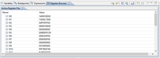
The values in R0 and R1 are correct, the mask in R2 is good and the result in R3 is good.
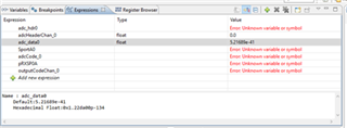
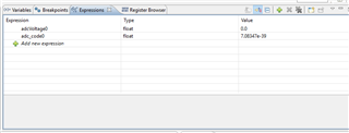
Why is it always saved to a float?
Thanks
Dan
Hi Dan,
The assembler doesn't know what the type of an assembly defined variable is. I'm not certain of the reason why, but for floating-point parts like the SHARC the debug information uses float by default for variables in the debug information it generates. As you see these variables will be displayed as a float in the expressions window.
You can either:
- define variables as global in a C source and make then .extern in your assembly.
- Modify your expression use to take the address of adc_data0 variable, cast it to int * then dereference it, i.e.: "*(int *)&adc_data0"
Regards,
StuartS.
Tried a quick experiment using the following code;
R0 = dm(RXSP0A);
R1 = dm(RXSP0B);
R3 = 0x00000000;
R2 = 0x00ffffff;
R3 = R2 And R0;
dm(adc_code0) = R3;
R4 = dm(adc_code0);
The value stored in R4 is the same as the value in R3, but the display of adc_code0 is not the same. Not sure why the Expression view in the debugger displays it as float, if anyone has answer that would be great.

Hi Stuart,
Thank you for the suggestions, I implemented the first option and I get the expected results. Would you please explain the second option a little more, is this done in assembly, C, inline?
Thanks
Dan
The second suggestion is to modify what you insert into the expressions window left hand column so that you display a variable using the desired type. This would not have required a change to the source code.
The assembler only inserts 2 basic types into the debug info, namely int and float, and it gives variables a float attribute type by default.
When displaying a variable in the expressions window if you insert "adc_data0" the debug information type will be used in the display. If however you insert "*(int *)&adc_data0" (without the quote) you'll see displayed the value of adc_data0 as an int.
Regards,
StuartS.
Stuart,
Thanks for the help it is appreciated. One more question (I hope) I have been trying to use the extern keyword with an array to no avail. I am declaring an array in the C file and filling it in the assembly code.
code snippet from the Header, C file and assembly;
SPORT.h
/* Default Buffer Length */
#define BUFSIZE 10
C source file;
#include "SPORT.h"
long adcCode0[BUFSIZE];
assembly file
#include "SPORT.h"
.extern _adcCode0[BUFSIZE]; Syntax Error at "["
R13=BUFSIZE;
// read SPORT0 until array is full
DO Label UNTIL EQ;
R0 = dm(RXSP0A);
R3 = 0x00000000;
R2 = 0x00ffffff;
R3 = R2 And R0;
dm(_adcCode0[R13]) = R3; Syntax Error at "["
R13 = R13 -1;
Label: nop;
Thanks again,
Dan
Hi Dan,
I would be inclined to implement that loop in C rather than assembly. If you're not too familiar with SHARC assembly doing the implementation in C then looking at the assembly produced by the compiler (using -save-temps -Os switches) may be a good starting point.
Using this approach I created the following assembly version of your loop above:
// ...snip...
.extern _adcCode0;
i4=_adcCode0+BUFSIZE;
lcntr=BUFSIZE, do (pc,.endlp) until lce;
r2=dm(RXSP0A);
r2=fext r2 by 0:24;
.endlp: dm(i4,-1)=r2;
// ...snip...
Notice that the array address of the label is loaded into a DAG index register and that address is post-modified each iteration of the loop.
Regards,
StuartS.
Please log in to reply.