Automatic gain control using ADAU1701
We are going to implement the ADAU1701 within an industrial application which contains an audio processing.
There is a need to configure an automatic gain control (AGC), but this DSP-type (ADAU1701) does not offer an AGC toolbox.
We are searching for a schematic, which will perform the AGC functionality.
We would like to receive your support.
HAPE
Audio Signal Processors
SigmaDSP Audio Processors
adau1701
Hello HAPE,
I am looking into some options for you. But first, can I ask how you want this to behave? There are limiters that will lower the gain if the audio gets too loud but does nothing to the audio below the threshold. Then there are compressors that will pretty much do the same thing but with a lower ratio so it is not as severe as a limiter but is still not what I would call a true compressor.
Then there is a true compressor that will lower the gain when the audio is above the threshold and increase the gain when it is below the threshold. Most AGC circuits in radios do this but audio engineers in pro audio often do not understand this concept. Usually you need to couple this with a gate so that the noise floor is not raised too much when there is little or no audio. This is the squelch circuits in radios.
So are you looking to only act on the audio that is above the threshold or act on both sides of the threshold with a band in the middle where the audio gain is unchanged?
Is the application mono or stereo? If it is stereo then is it true stereo signal or just two channels of independent audio?
Thanks,
Dave T
Hello Dave T,
thank you for your response. In our application the following notes are essential:
ad.1 the input signal is usually true stereo but within the DSP there are two audio signals beeing processed independently.
ad. 2 some audio equipment of the user ( e.g. various and variable 2 CH audio sources) will then be connected the input of the DSP. The user may as well change the volume during listening to his audio.
ad. 3 the further signal processing within the ADAU1701 contains several blocks which are functioning as: low pass filtering, dynamic compression and modulating a 500Hz sinus signal.
ad. 4 the desired functionality of that circuitry is generating a low pass envelope signal which will be used to modulate a 500Hz sinus signal.
But the parameter settings within the two independent audio signals are different (e.g. different cut off frequency of the LP and different slope of the compression). Two modulated 500Hz signals are then the DSP output and serving as an input for further electronics. This function is working properly.
ad. 5 the reason for the additionally desired automatic gain (AGC) control functionality is to maintain a constant output level, even when the volume of the audio input is changed.
We would appreciate your options.
Thanks
HAPE
Hello HAPE,
Thanks for the info. I think the first thing to try is simply a compressor limiter set to a really high ratio and the threshold set really low. So most average level signals will be compressed a good 20-30 dB. Then after this compressor you add around 20dB of gain to compensate. So if the signal goes any higher it will simply compress more and more and the level out will stay about the same. Then when the signal goes down be gained up a good 20-30 dB to try to keep the output the same and then it will eventually start going down so the noise floor when there is no signal will not go up too high.
This will require some adjustments to suit your needs like with the release and hold times.
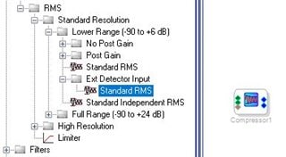
I made some quick adjustments using music and it seemed to work well. I can adjust the input level around 20dB or more without noticeable change in the output volume. In this example project I put an input volume control in to be able to experiment with it. The only parts you need for your project is the Compressor and the volume control after it. The compressor is the RMS--> Standard Resolution --> Lower Range --> Standard Independent RMS.
I chose this one because you can link the two inputs if desired or run them independently. Hopefully you have enough MIPS left in your project for this. Compressors take a fair amount of resources. There are some other ones that are more lean but this one I like.
Dave T
ADAU1701 AGC Example.zip
Hello Dave,
thank you very much for your helpful support and we really appreciated your solution path which is using a compressor in order to create an automatic gain control function.
We were testing now several transfer functions within that compressor as well as selecting different attack and release times. We observed that the attack and release times had to be chosen quite long in avoiding distortion artefacts and "pumping".
From now on we are going to insert these AGC blocks into our recent project. Our prospective practical experince will show if that AGC is working efficiently and does as well not exceed the resources of ADAU1701 and its MIPS.
But there again, another basic approach for designing an AGC with ADAU1701 should be examined as well.
We conclude that a servo control mechanism e.g. a closed loop control is required, because the amplifier circuitry must have the "kowledge" of the desired output amplitude in order to properly adjust the gain. It follows then, that an AGC requires feedback as well as a variable gain amplifier (e.g. VGA).
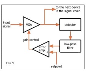
The very basic architecture for a closed loop AGC-system in principle consists of an VGA, as a next device to the audio input within the signal chain. The VGA determines the amplitude A and adjusts the gain accordingly. The amplitude B measurement is performed by a detector block (different detector types might be used and for the purpose of enabling a proper attack and decay behavior in order to reduce the control speed e.g. RMS, envelope detector, logarithmic etc.). The output of B is then compared to a desired reference Bref. By means of a feedback block that "error signal" will control the gain of the VGA.
In our application the AGC should be a feedback circuit that takes the maximum level of the modulated output signal (as a reference Bref.) and controls the gain of the input signal.
If you don´t mind my asking this, is it possible at all to design an AGC which is operating on a closed loop circuitry by using the tools of ADAU1701?
We would be glad to have your proposal for solution.
Many thanks
HAPE
Hello HAPE,
You are correct that you have to set the time constants for your type of program material. I did leave that for you to do since setting something up for music can be very different if it is for voice only. Etc. Anyhow,...
I do not have time to work up an example but what you can do is use a compressor with an external sidechain input. The rectification and time constants are still being calculated in the compressor cell so you do not have to do this outside of the compressor cell, but, if you do you can just set the internal controls so they are out of the way of the external controls. Like a slow attack and fast release.
Here is where you can find the cell:
The extra pin is the sidechain input.
Here is a quick picture of one way to do this. I set this on the output of the compressor since it seems like you desire a feedback style of compression. To do this you must use a feedback cell at some point in the sidechain to avoid a compiler error. It sets up a one sample delay. In this example I only summed the two channels and then used an external volume control to realize a threshold/compression level adjustment outside of the DSP. You can implement anything you like in this chain. You can EQ it for a De-Esser or to make it not respond to low frequencies.
We have peak and RMS envelope generators, log functions, comparators etc. So you should be able to do what you mentioned however, I think you will run out of MIPS.
If you really need to develop all this outside of the compressor then Instead of using the compressor cell you may only need to use the externally controlled volume control as your gain element. It has a slew control to control the zipper noise but that will limit the speed. Again, you will have to make adjustments.
On the forum there are lots of example of circuits to do parts of what you describe. Others on the forum may chime in and help. It is an interesting problem but I have to take care of other deadlines at the moment.
Dave T

Hello Dave,
thank you very much for your recent advice according to our AGC problem.
In the meantime we have tried several different circuitries using a compressor cell and as well a feedback loop with an externally controlled gain element.
The feedback circuit takes the maximum output level as a reference input and controls the gain of the input signal with the cell SW vol 1. The moving average block AvgEnv1 is used for reducing the control speed and the limiter Limiter 1 limits the gain to -6dB in the case of no or very low level audio input.
But up to now we did not get a satisfying result on that AGC functionality which will meet our demands.
Using this less efficient recent design on ADAU 1701, we have compared the AGC performance with reference to different inputs e.g. a triangle test signal (as a source element) and the line output e.g. from a smartphone.
We could adjust the volumes of these input signals around 20dB without any changes in the output level. But it seemed to us that the AGC was more efficient for the triangle test signal as compared to the external audio signal. Anyhow that AGC control range was not sufficient at all.
In our application an AGC control range of about 60dB would be desirable, in order to maintain a constant output from the DSP which should be quite independent of the adjustment of the input volume controller.
Because we expect a much better AGC performance, which should be achievable by a feedback control circuitry, we believe that there was a probable error in our circuit design as a matter of principle.
We would appreciate your support in avoiding some possible bugs.
Many thanks
HAPE
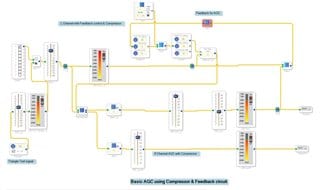
Hello HAPE,
Yes, there are some fundamental errors in your circuitry. The first problem is the understanding that this program is run every sample period with the current sample as data. I see you are using one channel of the compressor as a reference channel and the other for the desired audio. The reference channel has its own envelope generator and limiter followed by a volume control. Then you feed the audio that has its gain changed into the stereo compressor.
OK, Where to start?...
The compare of which is greater: This is comparing the current sample with the audio that has the gain changed. The audio sample can be anywhere in the sine wave and all this is telling you is if the gain control is adding or reducing gain and you are taking the greater of them. This is not really telling you what the RMS or average level of the audio is. This is difficult to explain but in short it is not giving you the error feedback you are looking for.
The other little details is that there is similar processing going on inside the limiter black and the envelope follower block so it is somewhat wasteful of MIPS. So I think I need to simply discuss compressor topologies and other issues. Sorry, but this is going to be a bit of a text book explanation here.
You made the argument that there needs to be feedback. With compressors there are two basic topologies, feed-forward and feed-back. There are advantages and disadvantages to both. With music recording, most of the classis great sounding compressors used for full bandwidth music (as opposed to a single instrument) are the feed-back style of compressor. These are also great for vocals. The characteristics is that they will let through quick transients since the control of the gain element is taken from the output so therefore when a loud signal comes in it is already sent out before the gain element has time to compensate for it. This has a pleasing sound with some material but if you are guarding against clipping or sending audio over a radio transmission and absolutely must NEVER clip the signal this is not a good topology to use. The signal Will clip since it is already gone before you can act on it to turn it down. Another downside is that there needs to be a lot of gain in the sidechain since when the signal gets loud the output gets compressed, it is lowered. So if it gets a little louder the gain change needs to be further lowered so a very small change of output level will cause a lot of gain change. This makes it easy to set up an oscillation especially in old analog compressors that have some phase shift and group delay. So usually these styles of compressors will only change the gain around 20 -30 dB max. Any greater depth will start to risk oscillation.
So the feed-forward design removes all these issues. The audio to the sidechain is fed from the input of the gain change element not the output of it. So it will track the actual input level always and set the gain reduction accordingly. With this topology you can setup a high compression depth of 70dB dependent on the gain change element. In the analog world it is usually a VCA that does this but in the DSP world you can get even more gain reduction if you desire. It is only math.
Now let me discuss limiting verses compression and AGC.
For music applications in recording studios they look at limiting and compression as being different but they really are not. They both reduce the level of a signal once it is gone above a certain threshold of level. Then a limiter will be very aggressive and keep the level very close to this threshold and not let it get any louder. A compressor will only gradually start to reduce the gain, so a small amount over the threshold will only result in a small gain change. A large amount over the threshold will amount to a larger gain change. This is the compression ratio, it is very high for limiters and less for compressors. However, both of these do nothing to the signal when it is below the threshold.
Here is where AGC comes into the discussion. I refer to this as "True" compression. This is where signals over the threshold are lowered in gain and signals below the threshold are increased in gain with the attempt to make the audio sit at the threshold level always no matter what the input level. These are commonly used with portable radios and voice communications. The audio must be louder than the high noise floor of a radio transmission and lot too high which will cause serious issues with the radio transmissions if the modulation becomes greater than 100%.
One other issue to discuss is attack and release times. These are often measured in milliseconds with attack times often down into the microseconds. Release times can be long and into seconds.
If you want to reduce a fast transient you will need a really fast attack time and usually a fast release time. This will reduce the transient but keep the rest of the audio fairly in changed. The problem with this setting is that for a low frequency signal it will treat the sine wave as a transient and reduce it. But the reduction will only happen above the threshold. Keep in mind the threshold is calculated with an absolute value of the sine wave. So with a hard limiter once the sine wave goes above the threshold it will lower the gain. This results in a clipped sine wave and lots of distortion. I can verify this when I have worked on several analog compressor designs in the past. A low frequency signal gets really distorted and sounds very bad. A 100 Hz sine wave has a period of 10ms. Taking the absolute value of this 100Hz sine wave gives you a 200Hz rectified wave. So it is rising for 2.5ms and falling for 2.5ms. So if you have an attack time of 10us or so, very fast and a release time of 1ms you will be horribly distorting the 100 Hz signal. This only gets worse the lower in frequency you go. At 20 Hz the period is 50ms. So this is why I usually do not set the release times to be less than 50ms or so. With one exception, if you filter the signal going to the sidechain. Then it will not react to the low frequency signals but then loud low frequency signals can get through.
So that I am saying here is that you MUST look at the level of the audio over many cycles of the waveform and calculate the level from this slower moving signal. The RMS compressor in our libraries have an attack time constant and a release (decay) time constant. They also have a hold time. This is where any new peak will be held for a period of time before it starts to decay.
Most of the other compressors and limiters have an instantaneous attack time which is possible with a DSP and not possible with analog circuitry. This can be handy with some applications where you absolutely cannot go above a certain level.
So the settings of these times is very dependent on the type of audio material you are sending through. So what is your application? If it is voice then I suggest you filter the audio to remove low frequency content so it will not cause the compressor to pump too easily and you can set faster release times.
It seems from your earlier posts that you are looking for an AGC circuit not a compressor or limiter.
So for an AGC circuit to work you need to have the ability to increase or decrease the gain around a desired level.
So if you want a desired level of -14dBFS with a 24 bit signal. Actually, let me use -10dBFS to make the math in this example a little easier.
So you want -10dBFS audio level out not matter what the input level is. (We will discuss noise and no desired audio signal later)
Then you want a range of 60dB of gain or gain reduction.
So an input signal that is -70dBFS in level will be increased in gain by 60dB so that it is coming out at -10dBFS.
In contrast, a signal coming in at +50dBFS, would be reduced in gain by 60dB to output at -10dBFS. As you see, there is a problem here in that it is impossible to have a digital signal above 0dBFS however, in the DSP core it can go about this level because we have 28 bits in the ADAU1701 core. So there is an additional 24dB available in the core. So if you are using EQ you can boost the signal and get a signal that is 24dB over the digital zero of a 24 bit signal. So in the case of the AGC it can be reducing the gain by 34dB and still be fine with no clipping.
So to be realistic about an AGC that you want to have a range of boost or cut you will need to reduce the level of the signal coming in. It is good to use the 24 bit signal for this and ignore the headroom in the DSP core since you have to leave the core with a 24 bit signal. So here are my numbers with an assumed range of 60dB and 14dB of headroom of a 24 bit signal.
I like -14dBFS as a nominal level. So really we only need to compress an input signal by 14dB since there will never be an input signal over 0dBFS. So really the 60dB range is needed in the gain boost side of an AGC. So perhaps this is best dealt with separately. Here is where we need to be creative.
So I will work up an example. It will take a bit to design and test.
So can you answer if your application is music or voice? And do you need a true AGC circuit like I described?
Thanks,
Dave T
Dear Dave,
we accept your detailed elaboration and useful information with thanks and as well your description of some fundamental errors within our circuitry.
In avoiding any misinterpretation of the desired AGC functionality we would like to clarify our underlying application once more.
We have developed a specific DSP-circuitry on ADAU1701 which is provided in a separated DSP-unit that takes the stereo audio output from any smartphone and will implement a specified signal processing in order to drive some other non audio devices subsequent to the DSP. These audio files from the smartphone will normally contain any type of music.
The audio signal processing of one individual channel within the ADAU1701 comprises several building blocks such as: low pass filter, envelope follower, dynamic compressor, sinus oscillator source and modulator. Out of this audio signal a slow envelope signal is generated which will modulate a 500Hz sinus signal. Thus the output will be an amplitude modulated (AM) signal which is used as a control voltage for some following other devices. This dynamic compressor is applied in order to reduce the higher dynamic range of the different audio signals to the very limited dynamic range which is essential for the control voltage.
Hence the modulation depth and the amplitude of the control signal must be unchanged even if the user of the smartphone will vary the settings of his volume control by hand.
This is the reason for the additionally desired automatic gain (AGC) control functionality within that circuitry.
In the following we will try to form a concept on this issue. Please rectify my proposal if i am incorrect !
As we know from analog AGC circuits (as shown in priciple in Fig.1) a VCA as a gain changing element is implemented within a feedback circuitry.
According to the DSP world it is understood that this program is running every sample period with the current sample as data.
But in our application, as distinguished from standard AGC practice, the user of the smartphone will not change the volume control settings permanently or in rapid succession by hand. Thus a practical gain control mechanism may act only very slow and should just compensate the very few volume changes the user has done occasionally.
As you have already stated, we must look at the level of the audio signals over many cycles of the waveform and calculate the level from this slower moving signal. In my opinion we must not design a "true AGC" because this processing should only run any gain adaptions to occasional sound volume changes.
Maybe a solution could be designed for ADAU1701 as well by interconnecting some suitable blocks which might have a matchable functionality to the underlying but unknown topology of an actual AGC cell that is to be found in the library for ADAU1442.
We hope that we could acceptably specify which task should be fulfilled in our application and we would really appreciate your further assistance.
Many thanks
HAPE
Hello HAPE,
I worked through many ways to do this and finally settled on this solution. I am pleased with the results. It tracks the set reference point very well but still does it slow enough to not affect the audio too much when listening to music. I do hear the compression but it actually sounds good!
I did change the topography of the design. You showed a feedback style of compression but it posed too many complications so I changed it to a feed-forward topology. Just do not place much if anything between the place where the audio is summed and sent to the sidechain and where the gain element is located.
I documented this in the schematic using comment boxes. Feel free to ask questions.
I will also attach the table text files in case the ones in the project are somehow damaged. There was a lot of time put into obtaining those values.
Dave T
ADAU1701 AGC Example with Target Level Setting.zip
Fullscreen
RMS Table Values.txt
Download
-7.2
-6.9
-6.6
-6.3
-6
-5.7
-5.4
-5.1
-4.8
-4.5
-4.2
-3.9
-3.6
-3.3
-3
-2.7
-2.4
-2.1
-1.8
-1.5
-1.2
-0.9
-0.6
-0.3
0
0.3
0.6
0.9
1.2
1.5
1.8
2.1
2.4
Fullscreen
Linear Interpolator Table Values.txt
Download
0.000251
0.000355
0.000501
0.000708
0.001
0.001413
0.001995
0.002818
0.003981
0.005623
0.007943
0.01122
0.015849
0.022387
0.031623
0.044668
0.063096
0.089125
0.125893
0.177828
0.251189
0.354813
0.501187
0.707946
1
1.412538
1.995262
2.818383
3.981072
5.623413
7.943282
11.220185
15.848932
Dear Dave,
many thanks for your tremendous effort in order to design that present solution on that AGC issue.
We highly appreciate your recent application, which is running very well now on our evaluation board.
But unfortunately our own interim development of a feedback controlled AGC on ADAU1701, e.g. as in the style of a common analog circuitry, has always failed and we still don´t know for what reason?
At next we will try to implement that AGC block in our project. We hope that this circuitry does not take a high amount of resources and we will have enough MIPS left for the completed project.
Thanks once more for your skilled help
HAPE
Hello HAPE,
I would have to look at your project again to remind myself what was the problem with it. My early attempts were to take what you were trying to do and correct it. The problems I kept running into were related with number formats. Some of my attempts had to use different circuits if the gain was above or below threshold and this started making it really complicated and used a lot of MIPS.
The solution I sent over is fairly simple in construction but the RMS detector and Linear Interpolator both use up a lot of instructions. It is much lighter than other solutions since it uses tables instead of doing the calculations.
If you end up using too many MIPS then I would be glad to look at your project to see if there are places to save MIPS.
Dave T
I have done an AGC on the 1701 which works very well with any kind of music material. Your AGC needs a fairly fast attack and slow release. The only thing you need to do is take a RMS compressor and set the ratio to the highest level so it acts as a limter. Then set the threshold to -20dB, attack to 400mS, hold 400ms and release 2000mS. After the compressor add 20dB of gain. Any level above -20dB will output 0dB.
The solution posted by Dave T works quite well in compensating for widely varying audio levels encountered while viewing various video streaming services commonly found while watching a given source. Commercial insertions are often 6 dB (or more) 'hotter' than the entertainment or non-commercial audio on a given source. It would be ideal to have a noise gate or gain freeze when audio drops down to the noise floor or a given threshold.
Thanks Dave T for your work in developing the lookup table/text files for the AGC gain.
Please log in to reply.