ADAU1701 TAC
Hello Engineer Zone Community,
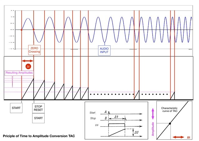
Using the ADAU1701 we are in search of a recent application which should comprise a simple Time to Amplitude Conversion (TAC) within an audio processing circuitry.
The TAC (start/stop type) should generate a linear voltage ramp, where the ramp (e.g. sawtooth oscillator) is started and stopped by a trigger pulse which is synchronized with the value cross detection from the audio input signal.
So the varying periods ∆ t are defined by the successive zero crossing timing. The resulting TAC should generate a corresponding level of the output signal.
For constructing a TAC system design by using the available building blocks of the ADAU1701 we are searching for a schematic, which will perform that TAC functionality.
We would appreciate to receive your support.
Thank you very much in advance.
HAPE
Audio Signal Processors
SigmaDSP Audio Processors
adau1701
Hello,
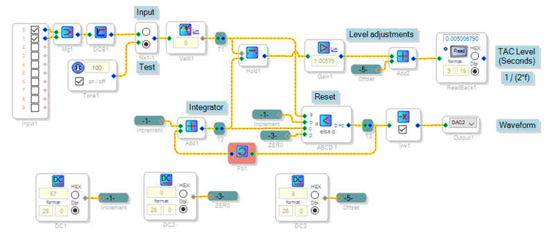
An adder feeding back to itself can make an integrator which increments its output with each sample interval. Having each zero crossing latch and then reset this integrator provides the desired TAC function. In the circuit below, the sine wave oscillator Tone1 provides a known signal for testing (a ADC input is also shown but I didn't try it). Adder Add1 adds the source DC1 to itself (via Fb1) each sample interval (96000 times per second) until the next zero crossing resets it via comparator ABCD1. The resulting waveform is output to DAC2, and its peal level, caught by Hold1, is available at ReadBack1.
The present sample rate of 96K can resolve time to (1/96000) = 10.4 uS. DC source DC1 sets the integrator's increment size. To achieve a a peak output measured in seconds, the integrator must reach an output of 1.0 decimal or 2^23 integer after 96000 samples. The needed interval is thus (2^23) / 96000 or approx. 87. The scale and offset adjustments at Gain1 and Add2 compensate for the inexact value of DC1 as well as a one-sample time loss in the integrator.
The attached project runs on a ADAU1701MINIZ board.
Best regards,
Bob
TAC.zip
Dear Bob,
thank you very much for problem-solving and implementation of your TAC circuitry.
As our functional test showed the converter runs very well on our ADAU1701MINIZ evaluation board.
Prior to your support i have tried to design a TAC by myself using a zero crossing VaX1 and a sawtooth source and some logic blocks. But these attempts were in vain because we did not discover any approach for making a gate or integrator function by means of the available building blocks. Now we have received your smart solution and we are perfectly satisfied. Thank you!
HAPE
Please log in to reply.