ADAU1701 no output on internal DAC's
Hi,
I made the following Project "DSPRiaa-I2S in".
The I2S Input is routed to I2S out and the digital Signal is ok.
However for easy measuring the signals i wanted to put the Output
to the internal DAC's as well, but to no avail.
I have 1.5 Volt DC Offset on the Outputs, but no Signal.
To test i made the Project "Test-Sinus" with a 1kHz Sine Generator
feeding the I2S Output and the 4 DAC's. The Signal is on I2S but None is on the DAC's.
I think that the Problem is in between my eary, but i can't find the error.
After that i inserted a 0.5Hz squarewave oscillator routed to MP7 but there is also no Signal present, just 3.3Volts
Any hints ?
Thanks in advance
Michael
0878.DSPRiaa-I2S in.zip
7776.Test-Sinus.zip
Audio Signal Processors
SigmaDSP Audio Processors
adau1701
Hi Biti. I am a beginner on this. I'm actually ended up here because of the lac of documentation onlye regarding SIGMA STUDIO for programing the ADAU1701 regarding audio processing. I'm setting up a small project that if it works out i might be able to produce with great quality using the DSP instead of Passive Crossovers. If you could help me with understanding the Sigma program and it's functions i would be much appreciated.
Sorry for bothering without having an answer for your question.
Hello Michael,
Your 7776.Test-Sinus project produces audio output from at least DAC2 and DAC3 on a ADAU1701MINIZ eval board. Thus, your project's settings are not preventing DAC output. The MP7 output difficulty can be fixed in your SigmaStudio project -- for an explanation of what's wrong and how to fix it, see https://ez.analog.com/dsp/sigmadsp/f/q-a/114099/zero-comparator-for-adau1452-sigmastudo-v4-2 (though for a ADAU1452, this also applies to the ADAU1701).
Best regards,
Bob
Hello Bob,
thank you for the response.
I don't own an EVAL board, I made my own PCB's to finish this project:
https://ez.analog.com/dsp/sigmadsp/f/q-a/64214/adau1701-riaa
after a long time.
I checked my layout and everything seems to be ok.
I soldered the ADAU1701 by hand and it seems I partially bricked the chip
or did not solder all the pins correctly. Are there any dedicated pins to check why
only the analog outputs are not working ? I checked AVDD and the two Filter Caps and
they seem to be ok.
I managed to get MP7 blinking according your explanation but not the Real Time Display.
Does it only work when the hardware is connected to Sigma Studio ?
My Hardware is in Selfboot Mode.
Kind regards
Michael
Hi Michael,
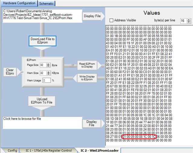
Sorry for the difficulties you're experiencing. Yes, the Real-Time Display reads from the hardware. I tried downloading your self-boot file E2Prom.Hex to the eval board's E2Prom using SigmaStudio's E2Prom Loader and it ran fine -- showing there's nothing wrong with this file:
The circled bytes at the end of your program forms a command to write to the Core Control Register at address 0x081C. The data written to this register, 0x001C, clears the registers and turns ON the ADCs and DACs. Thus if these bytes are missing from your E2Prom, you'll get no sound from the DACs.
The very last byte, 0x06, is the command to stop loading from the E2Prom. How are you programming your E2Prom? Can you verify its contents vs your file? If your E2Prom is correctly programmed from your file, then it's likely you have a hardware issue. Only thing -- so much of your hardware is working that I can't think of a hardware problem which would affect only the DACs. Your ADAU1701 comes out of reset, its crystal oscillates and its PLL locks, and it's running your code. And the DACs are correctly biased at Vcc/2. So it's unlikely that all the DACs are damaged. I just hope you can get it working!
Best regards,
Bob

Also check across your capacitors connected at pins 40 and 41 on your ADAU1701 -- both should read about 1.5 volts. If you wish, you could post your hardware schematic and/or pcb layout so that someone here with HW design experience could examine it. The fact that your crystal and PLL are working suggest that you did well in your layout of bypass caps and such. BTW, making your own board and having most all of it work is quite a feat. It's something that I haven't attempted at home. For example, my last hobby project was a wah-wah pedal for a young friend -- it could have been made with a ADAU1701, but I went with a typical quad op-amp design from the '70s.
Hi Bob,
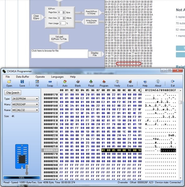
this is the readout of my E2Prom.
It looks same to yours. I will check across the caps and recheck my layout before posting it here.
Michael
Hi Bob,
a little late,
it Looks like I bricked the chip.
At pin 47 (FILT_A) there is no voltage, so no output on the dac's.
Finally I will have to redesign my board because of some issues regarding I2S in
and synchronous masterclock discussed somewhere else here.
Thanks for your help.
Michael
Hi Bob,
I read the datasheet again and the Blockdiagramm shows, that pin 47 (FILT_A) is
only responsible for the ADC's and FILT_D for the DAC's, where I have 1.5 Volts.
There is one different thing in this design compared to my earlier designs, where
the analog outputs are working.
Because I do not need the analog in's I omitted the 18k resistor from pin 3 (ADC_RES) to ground
but left ADC0, ADC1 and ADC_RES floating. Could this be my problem ?
Thanks for your help.
Michael
Hello Michael,
It is not a great idea to leave these all floating but I do not think it would cause the DACs to stop working. I must admit that I have not tried it.
Have you dropped in an oscillator block into the schematic and run that through a volume control and then to the outputs? This is a good test to see if the outputs are working. The reason why you use a volume control is because the output of the oscillator is at full digital zero. So turn the volume down about 30dB before you turn it on. Then turn it up afterwards.
When you try this I suggest you disable the serial ports, you will need to supply the part with a master clock but that is it.
I recall that this part has a behavior that if you give it clocks that do not divide properly then it will mute the audio.
Dave T
Hello Dave,
BULLSEYE
your recall about the behavior of the DSP made me think about my first steps getting
the prototype working.
I hade two different masterclocks, one quarz for the DSP and one oscillator for the
external ADC. I measured the analog outputs but got no signal. I tried different things
and measurements according Bobs hints but the outputs won't work.
After that I plugged in my external DAC and had very bad distortions, sometimes no
audio signal at all. Reading different blogs I learned that the -1701 will not sync to the
input bitclock, so I removed the quarz and fed the DSP from the ADC masterclock and
from there everyting was fine.
At that time I had already given up the analog ports and never checked them again.
Yesterday I did a new test and found them working properly, what a shame.
So you are right, because of my clock issues they were only muted.
Let me say thank YOU and BOB for your support and sorry for taking your precious time
for such a stupid mistake.
And on the final PCB there will be ADC0 and ADC1 tied to ground via 1k.
Btw. there should be a DONATE button on this site.
Kind regards,
Michael
Hello Michael,
You made an error that is easy to make. I have certainly done my fair share of duh? mistakes!
You did well helping us figure this out by giving us plenty of information and being patient with the process.
I hope the rest of your project goes smoothly.
Dave T
Please log in to reply.