ADAU1701 I2S-2 OUTPUT WAVEFORM PHASE INVERTED
Hello again, This is a same report as I post before (It was flagged and rejected treated as a SPAM post)
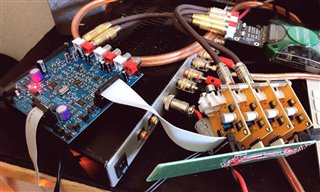
I have developed ADAU1701 single board which has three I2S output features.
I connected three external DAC Boards like this way...
All boards output are working but the DIG4 and DIG5 output waveform was inverted.
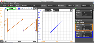
So I checked the external DAC output waveforms on SDATA_OUT0 and SDATA_OUT1
There are no problem (In phase)
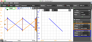
Then I checked the waveforms on SDATA_OUT0 and SDATA_OUT2
Completely Inverted output comes form SDATA_OUT2.
I also checked with another DAC Boards, but the result was the same.
I guess something wrong on my SigmaStudio4.4 or ADAU1701 chip.
Does anyone had checked like this ?
Add a Link to Board description Information.
[edited by: Cyberpit at 3:37 PM (GMT 0) on 10 Aug 2019]

Hello Cyberpit,
I think your question is actually answered in the datasheet in the Audio DACs section:
The DACs are in an inverting configuration. If a signal inversion from input to output is undesirable, it can be reversed either by using an inverting configuration for the output filter or by simply inverting the signal in the SigmaDSP program flow.
The DACs invert the signal so if you are comparing to the built in DACs that could be the problem.
The external DACs might also be the issue.
If the serial data is are going through an inverting buffer between the boards this also will invert the signal.
SigmaStudio itself will not invert the signal unless you build it into the program schematic and the hardware does not invert the serial port signal so it must be in the details of the DACs or the interconnection.
Dave T
Hello Dave-San,
Thanks responding.
You didn't catch my posted point. My point is SDATA_OUT2 output is the only different from others.
I'll verify this matter again. Then detailed evidences will post here.
Now I am back, verification had done!
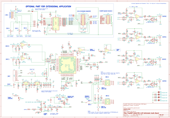
Before showing wave-forms, please have a look of my ADAU1701 board whole schematic...
This is complete schematic circuit diagram of my design. Embedded DACs has phase inverted LPF output. As a result of this, My design has absolute phase transparent feature (I've read datasheet carefully before start the design...) I2S output header has NON-invert output buffer for driving the external DACs. This means output I2S data signals are NEVER be a 1's Complement (in Logically non-inverted signals) Ever.
Here is tested SigmaSuddio Schematic
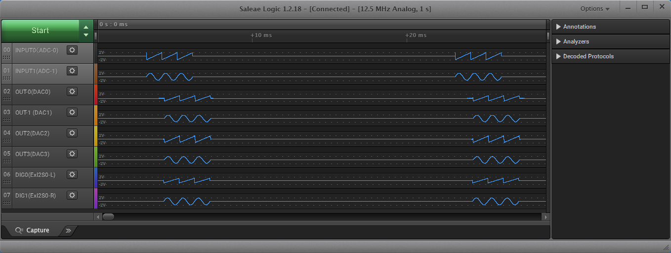
I tested this board with following equipment. Signal source is Analog Discovery2, Waveform Captured by Saleae Logic8. I used gated Up-Ramp Sawtooth Waverform (for LEFT) and Tone-Burst Sinewave (for RIGHT)
Following captured waveforms are Analog inputs to Each Analog Outputs.
Part1 (Souce Waveforms, Enbedded DACs, External DAC #1)
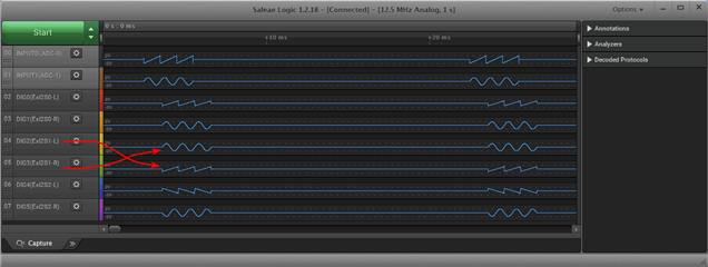
Part2 (Souce Waveforms, External DAC #1, External DAC#2, External DAC#3)
Can you see two waveform traces are inverted from the bottom? My board don't have 4th external DAC. So I checked I2S (I8S) Signals in Logically...
Here is Schematic. Source was changed to 12kHz Triangle Generator to avid the noise awareness.
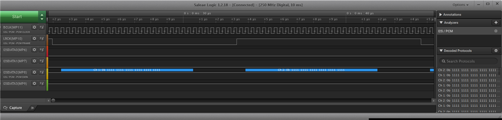
Captured Logic Signals (BCLK, LRCK, SDATA_OUT0, SDATA_OUT1, SDATA_OUT2, SDATA_OUT3)
24bit I8S Digital Zero:
"Digital Zero" is not a Digital Zero output...
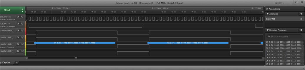
24bit I8S Plus Maximum:
24bit I8S Minus Maximum:
Now you can see the whole facts. SDATA_OUT2 and SDATA_OUT3 are completely 1's complement (Not 2's complement) . Following non-data space shows there's some kind of "logic inverter" device must be required, but there are nothing at all. (Please see my schematic design again)
I would like to know the WHY? Are there any notes in Datasheet? Application Notes? Erratas?
I gonna make 4way Crossover Dividing Network for my own Audio system, but this behavior must be a serious problem for me, also other ADAU1701 users.
Can't you see what I mean? Dave-San



Hello Cyberpit,
FYI, the data in your screenshots are 2's compliment numbers. The MSB is the sign bit. When it is a "1" then the number is negative. When it is a "0" then it is a positive number. So a MAX positive number is 011111111111... and a max negative number is 10000000...
A zero is zero in all formats and if you subtract "1" ( one LSB) from zero you will get 111111111... which is one bit negative from zero.
Now on to your issue.
I think you have the data inverted in the register settings. I went into the lab and took some screenshot. All of the serial data output ports all put out the same number when fed the same data.
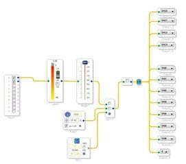
Here is my SigmaStudio program. I sent the exact same data to all outputs.
I gave myself options for selecting three different sources. The ADC, a square wave of different duty cycles and a DC source. The DC is the most handy to use since you can input any number in two different formats.
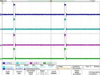
When I send a -1 in 1.23 format we get the sign bit as a "1" and all the rest are zeros which is a full scale negative signal.
The four traces you see are from top to bottom, ( all serial output ports)
SDATA0
SDATA1
SDATA2
SADTA3
You can see they are exactly the same. no Inversion.
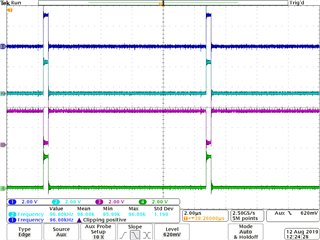
In this next screenshot you see that SDATA2 is inverted. It is putting out the sign bit as a zero and all the other bits are a "1". This is a max positive number so this is the correct inversion for a 2/s compliment number. The inversion is a 1's compliment but the data is in 2's compliment form.
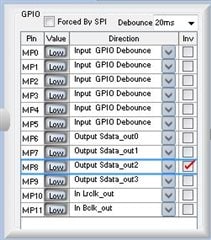
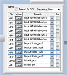
This next screenshot shows the register settings that produced the inverted output on SDATA2
Note, the "Inv" button is checked which inverts the data.
This next screenshot is what produced the first scope shot with all the data the same.
So I am guessing that the GPIO invert register 2081 (0x0821), which holds the nibble for MP8 pin, is not 0b0100 but it is 0b1100 which inverts the serial port.
Dave T
Hello Dave-San,
Thank you for answering my question.
2's complement and 1's complement has always differences 1, so in 1's complement of Zero will shift to -1 .
Now I understand the reason why.
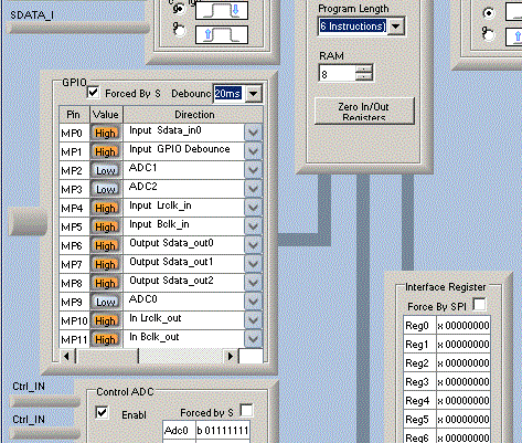
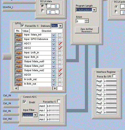
Maybe I have a GUI - issue (Please see my Screenshot)
I CAN'T see the "inv" option radio button !!
My computer is running in Japanese version Windows, so the GUI layout must be different from US-English version.
I can see the scroll bar under the GPIO section, so I scrolled it out ...
There's NO "Inv" text above the radio button. It was hard to know about this option.
That's why I couldn't solve this problem.
Now I could solve this problem and wishing this GUI issue should be fixed in next version SigmaStudio.
Dave-San, I'd like to say thank you very much.
Cyberpit
Hello Cyberpit,
Wow, this is a Windows issue for sure. I have never seen it like this. It might be a resolution setting? But, I am glad we figured it out!
I wish you well with the rest of your project!
Dave T
Please log in to reply.