Indirect Parameter Access Table cannot be used with ADAU1452
I want to use it for crossover block control via I2C. After completing link compilation in my project, it is not selectable.
I learned from the following link that it would be invalid in older versions of the schematic. Therefore, I recreated the project with Version4.2. It became valid once. But after restarting SigmaStudio, it will never be selectable again.
wiki.analog.com/.../advancedfwconfigs
My questions are:
1. Is this function of crossover block control available?
2. If it is not available, please answer how to change crossover block parameters via I2C.
3. How to restore the Indirect Parameter Access Table function.
Additional Information:
I use upsample and downsample blocks. I saw somewhere that they had bugs. But for my purposes these are very important and cannot be disabled. The reason is that FIR filter performance is important for high-end audio. To use this feature, the following options are disabled and compiled.
Audio Signal Processors
adau1452
SigmaDSP Audio Processors

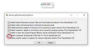
It solved. When USBi is connected on the software, the selection becomes valid. It doesn't seem to depend on whether you have USBi hardware.
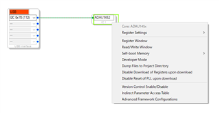
I will add a little more before this is closed.
CrossOver may be out of control from the Indirect Parameter Access Table. I don't yet understand how to use the Indirect Parameter Access Table correctly, but I'm worried about the very low memory consumption of the crossover.
I arranged a simple 2nd order LPF / HPF filter table. But that simple block consumes more memory for that than a crossover. Perhaps the filter is not calculated in real time by the DSP, but may have a table inside.
The actual implementation is unknown to the user. However, it seems to indicate that a crossover has a low load on both cycles and memory. This indicates that a crossover block may only have a single parameter at a time.
Isn't it impossible to change the characteristics later?

The crossover is implemented with simple IIR filters. You can find documentation on the Indirect Parameter Access Table here in the wiki. For a standard second order crossover, the block generates two sets of coefficients for the two second order sections, one for the LPF and one for the HPF. For the Linkwitz-Riley 24, you will see four sets of first order filter coefficients, two for the high-pass and two for the low-pass. Both memory and cycles are the same whether using the crossover block or building the crossover from individual filters (assuming you right-click and use the "grow" command). In your example, you are comparing both LPF and HPF to a single second order filter instead of two. Note that the '1452 takes advantage of SIMD instructions when filters are cascaded in a single block.
Regarding calculating the filter coefficients, you are correct in that the block does not calculate the coefficients in real time. SigmaStudio calculates the coefficients according to the formulas here. Changing the crossover filters dynamically is not a common or recommended use of the crossover block. If you need to do this, I would recommend using one of the filter blocks with hardware or software slew.
Ken
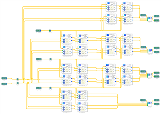
Thank you very much. However, the correct usage of the its function remains unknown. Instead, I set up a 4way crossover using a regular EQ block.
It has linkwitz 12 and 24 switching functions. The crossover can be set independent of the 44.1 and 48 frequencies. If this block can have 80 tables, a single EQ can provide full range functionality.
This worked fine at first. Currently it does not work. The cause is under investigation. However, it is out of the topic, so if I can't solve it, I will ask a new question.
Hello yohine,
I do not understand what you mean about the settings being independent of the 44.1 and 48kHz sample rates? The filters are calculated for a certain sampling rate. It will scale with the sampling rate which is good sometimes and not other times. For an example. If you calculate the filter coefficients for a sample rate of 96kHz and the filter has a notch at 8kHz. If you run this filter at 48kHz the notch will be at 4kHz. It will scale. The same thing will happen to your crossover. The crossover frequencies will change with the sample rate. The difference between 44.1kHz and 48kHz is not great and perhaps it would not be audible in your application but my point is that it will be different. If you do not want the crossover points to change at all then you have to have different coefficients for 44.1kHz and for 48kHz fs.
Dave T
I probably understand them correctly. In my structure all signals pass through the filter at 88k or 96kHz. The sample frequency is measured by external control, and the resample block is selected at the input section. However, the frequencies of 44 and 48 remain dependent on the input clock.
My concern is the frequency error of 44 and 48. The filter frequency will move when the master clock is changed. I am finding a way to solve this. Their frequency ratio is always 1.088. So I created a filter table with that ratio. The DSP should be at the correct frequency by selecting the next value in the table.
Is my method correct?
Hello yohine,
If I you are using index controlled filters you can set one filter to be correct at 44kHz fs and another to be correct at 48kHz fs and then switch between them when you detect the ratio changes in the ASRC register. This will work and it sounds like thisis what you are doing.
Why don't you simply run everything through the ASRC and clock the core with its own crystal at a constant rate? Then the ASRC will adapt to the incoming rate and you have to make no changes?
Dave T
Please log in to reply.