Poor frequency response - simplest config!
Hi all,
I'm used to running much older versions of SigmaStudio - now on to 4.4. Encountering something really weird. I have a small audio device I'm planning to EQ with the 1466 DSP. I measured the device with my measurement rig pre-EQ. Then I put the ADAU1466 dev board and SigmaStudio into the chain, create the easiest possible config to make sure everything is OK (wire the input directly to the output), compile/link/download and run the test again. No love!
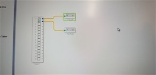
The first picture is of the config file schematic - I said it was easy!
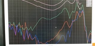
This shows the before and after:
The green line is before EQ/SigmaStudio/Dev kit, the red is after I plug the dev kit in the path. It looks like a first order high pass filter at about 10 kHz.
Any clues/tips about what's going on? I'm baffled - and I'd hate to have to just drop this kit and move on...
Audio Signal Processors
SigmaDSP Audio Processors
adau1466
[deleted]
Hi Bob,
When I do as you suggest, I get the red line; when I plug my headphones directly into the test system's output - I get the green line. It's not the test equipment that's in the way.
So to clarify:
test box output -> headphone = green line
test box output -> input 1 of ADAU1466 dev board -> config shown above (input to output) - > Output 1 of dev board -> headphone = red line
Not good. This is a straight pass-through configuration, it should be very close to the green line, as it is in-to-out, no processing.
Thanks!
Dan
Hello Dan,
DanWiggins said:
So to clarify:
test box output -> headphone = green line
test box output -> input 1 of ADAU1466 dev board -> config shown above (input to output) - > Output 1 of dev board -> headphone = red line
Not good. This is a straight pass-through configuration, it should be very close to the green line, as it is in-to-out, no processing.
Can you clarify your tests here? You said Output->headphone-> = Red Line. I would think your answer would be "= I do not hear it or I do hear it".
I suspect there can be an issue with the wiring. Are you going into a balanced input? I know with my Audio Precision Portable ONE I had to build adaptors to use when going from single ended to balanced inputs because with the input transformer if you leave one end of the transformer unterminated you get a really great high pass filter. No low end and lower level.
There are also many settings in the DSP serial ports and routing that can cause no output so to eliminate issues with the project itself I attached a known good project that I personally have tested with an eval board at my desk. I am taking the output from my MAC and I plugged a set of headphones directly into the eval board outputs. Steely Dan sounds just fine. Plenty of low end.
Another thought,... Are you driving a really low impedance by any chance?
Dave T
ADAU1466 Basic Stereo Input-Vol-Meter-Mute.zip
Hi Dave,
Driving a 10 kOhm input impedance - so a high impedance. Single ended inputs and outputs (APx515 and a Crysound 6151). I hear it - but it is way down and the frequency response is obviously skewed to the high end.
Thanks!
Dan
Hello Dan,
Sorry this comes so late but I am trying to clean up old things.
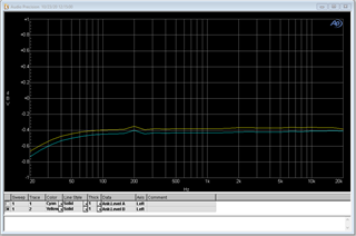
This is the frequency response I measured with the eval board using an AP2700. This was with it set to 100k load.
I did not normalize the curve to be at zero. But you get the idea that it is rather flat. The top and bottom scale is +1dBV and -1dBV so it is a fine scale.
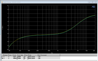
This graph is with the AP set to 600 ohm load. This is not really designed to drive this low of a load. The scale is +1dBV to -10dBV so this does show a lot of roll off. I would have to look closer at the design of the Op Amp drive circuits.
For comparison I took one of the older ADAU1452MINIZ boards to compare to and it looks much better driving a 600 ohm load. So I will pull out the schematics and see what is different between these two boards.
The low end roll off is what I would expect driving a 600 ohm load.
Dave T
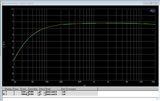
I did a bit more testing and determined that it is the DAC output that is where this is going wrong. There is a difference between these two boards, one has a single ended DAC output and the other codec is differential. So the amplifier and filter is slightly different so I suspect there is an issue there. I would have to simulate this to see where the issue it. The DSP is not the issue, it is the analog filter stage of the DAC that is the issue.
Dave T
Please log in to reply.