ADAU1772 SAI configuration for MCU
Hi, Im working on project where I have STM32 mcu and ADAU1772 codec, plan is to get readings from 4 analog signals and process them on mcu. I managed to link my sigma project with firmware. How do I setup input and outputs on adau1772 in sigmastudio (I2S or TDM)?
adau1772
Integrated/Special Purpose A/D Converters
Audio CODECs
Hello Maobuff,
This is a very general question so that makes it a little tough to answer. On the Hardware Configuration tab you will see some sub-tabs for Register Control. In that window there are even more sub-tabs for the register settings. There are many places where you will need to be certain that it is set properly. I cannot supply you with an example file without a lot more information of what you need to do.
So the ADCs will be routed to the Serial Output Port.
What format? Two pins for I2S to transmit the four channels in stereo? Will you want to use TDM-4 for the data?
What sample rate?
It is probably best for the 1772 to be the clock slave on the serial port, is that possible with your MCU?
Will you want to use the internal DSP core for the data going out? If not then will you be using it for the data coming back in?
Will you be using the DACs? Will you want to go directly from the serial input port to the DACs or through the DSP?
Then there are many other small settings that would require more questions...
It is best for me to provide you with a basic starting program that you can customize from there.
Dave T
I can probably configured MCU SAI for TDM-4 (Gonna check STM forums to make sure that Im doing it right way). I will stick with TDM-4 as format for now. Im not planning to use DACs. Im not sure about using MCU as master, because I cant configure "real audio frequency" to be exactly 48kHz. Im thinking to use MCU as slave. Im planning to use DSP later to cut frequencies, and making threshold for audio level. But for now I just need to get raw audio from all channels.
Edit: Also question about TDM-4: ADAU1772 have 24bit ADCs, so its frame length is 96 bit correct? Or its outputing 24bit value in 32bit (first or last 8bits are useless (0xFF or 0x00))?
Edit2: Im terribly wrong with configuration as master, I can configure MCU as Master with sync (MCU will provide master clk for adau1772)
Hello MaoBuff,
The 1772 serial port can be operated as a master so that is not a problem. It is just a little easier from a clocking standpoint to have it operate as a slave and let the ASRC deal with the clocking differences.
Most of the time TDM4 is configured with 32 bit slots for each channel. The data is left justified, (or delayed by one bit is really common) then you can fill in the data with as many bits as you like with no changes in software. 16 bits, 24 bits etc. This part the ADCs are 24 bits and the last 8 bits of the frame are no used and should be truncated in your application.
The frame length will be 128 bits, (32 x 4)
96 bits would be a packed format with only 24 bits per frame. On this part I would not get too creative. There are some bugs on the TDM interface and I think it will work OK with a packed format but I would want to look at it on a scope first.
Dave T
Settings 24bit per channel is not an option in sigmastudio, Its only allow 16 or 32 BCLK cycles per channel, while I can chose 16 or 24bits per channel data. I assuming that I have to deal with this later on MCU side(ignoring last 8 bits). Right now I'm confident enough in setting up data format on 1772, but can you provide simple project(TDM-4 32 cycles BCLK, 24bits per channel, 48kHz, ADCs to SAI configuration)
Edit: Is that a problem that I can't set SAI freq to be 12.288MHz, closest I can get is 12.235294, and after dividing to get 48kHz im getting 47.794kHz?
Hello Maobuff,
Do you have a 12.288MHz crystal for the ADAU1772 Master clock input?
I setup a project to give you TDM4 output as a master at 48kHz fs.
I also setup the LRCLK to be in pulse mode since most TDM inputs expect that. But you can change this in the register settings.
Dave T
ADAU1772__4ADC to TDM4 no DACs.zip
Yes, Im using 12.288MHz crystal. Today I mannaged to write registers from project that you provided to 1772, but checking with oscilloscope Im confused. BCLK is 256KHz, LR is 4KHz instead of short pulse (one BCLK duration), and ADC_DATA0/1 is constant 3.3V.
Hello Maobuff,
Something is wrong with the hardware. The project is setup for SPI communication so you might have to change it to I2C.
Check that the crystal is oscillating at the correct frequency.
Are you using SigmaStudio to directly program the part?
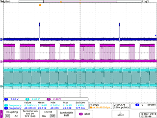
I went into the lab, hooked up my eval board and loaded in the program I sent to you and this was the result:
As you see, the LRCLK is at 48kHz, the bitclock is at 6.144MHz and the serial output 0 has four channels of data. I was only driving data into ADCs 3 and 4 so you can see that in the data.
Dave T
Hardware looks ok, crystal is 12.288MHz (checked with oscilloscope), I2C connected and cheked. I will provide schematics for my custom adau1772 board inside zip archive.
Im exporting *REG.h header from SigmaStudio (4.4 version) to MCU project. On MCU im setting up i2c and sai only and writing all registers from *REG.h header, nothing else. 1772 is accepting my register because Im getting bclk and lr after registers are set. Only thing that can be wrong is way Im writing to 1772(wrong order) or my SigmaStudio exporting wrong values
1772.zip
Hello Maobuff,
If you are just dumping in the registers in one large dump then this is probably the issue. Look at page 30 of the datasheet:
To program the PLL during initialization or reconfiguration of the codec, the following procedure must be followed:
1. Ensure that PLL_EN (Bit 7, Address 0x0000) is set low.
2. Set/reset the PLL control registers (Address 0x0001 to Address 0x0005).
3. Enable the PLL using the PLL_EN bit.
4. Poll the PLL lock bit in Register 0x0006.
5. Set the COREN bit in Register 0x0000 after PLL lock is acquired.
Control Port Access During Initialization
During the lock acquisition period, only Register 0x0000 to Register 0x0006 are accessible through the control port. A read or write to any other register is prohibited until the core clock enable bit and the lock bit are both asserted.
After the CORE_RUN bit (Address 0x0009) is set high, the DAC_SOURCE0 and DAC_SOURCE1 register bits should not be changed. If these bits must be changed after the ADAU1772 is running, the CORE_RUN bit first must be disabled.
I think you need to follow the PLL setup procedure then dump the rest of the registers into the part. You are probably missing a number of writes while the PLL is locking.
Dave T
Im not dumping all by order, first dac volume control, then pll in order that sigmastuido generated them(I adapted it to work with my mcu), then pause for one second, then all others registers. Maybe sigmastudio generated code with wrong order. I will double check this part.
You are correct. I made a misstake in code, and MCU was writing wrong registers.
What about registers that are not present in datasheet(Rev. C) like 0x0A(SLEEP_INST) or 0x60(ADC OPER) but they are created by sigmastudio. Do I have to ignore them?
Also I noticed(from .h file) that 1772 have program(I assume that is for dsp), Do I have to write it too? If yes, what is correct address for program (judging by .h header is 0x80(128), but is program uses different i2c address?)?
Why SigmaStudio generating wrong address, from datasheet I2C addresses can be from 0x3C to 0x3F, but SigmaStudio have option for 0x70, 0x2 etc.
Edit: I think address is shifted one bit to the left, because 3F shifted one bit to left is 7E, etc.
Hello Maobuff,
Register 0x0A probably should have been included in the datasheet register list. It is the DSP sleep control register. So it is OK to use but it is a little tricky to use. It is not a simple one bit register. It does default to zero and really should not be changed by the user. SigmaStudio is setting it up for the program that is being used. If you are going to load in the program then it will need to be written with the value that SigmaStudio is giving for that register. So Yes, write this register.
Register 0x60 should never be written to. This is a mistake for SigmaStudio to be writing to that address. What data is it writing to it? It really should be all zeros.
You do not have to write the program since you do not need to send data through the core.
The address given is the 7-bit address which is always shifted to the left by one bit to make room for the Read/Write bit. So that is the difference in the numbers you are seeing.
Dave T
0x0A is 0x00 and 0x60 is 0xA0.What about SOUT_CONTROL1 (0x35)? Its missing in datasheet too.
Also SigmaStudio generated reserved registers (0x42 with value of 0x00)
By core you mean using DSP stuff? Im planning to use DSP later, so knowing how to write program is important (for later use).
Hello Maobuff,
SOUT_CONTROL1, 0x35, keep this as zeros. It will default to zero so you do not need to write to it.
0x42 is reserved and even in my records it is listed as reserved. It will default to 0x00 so I would not write to it.
Yes, the core means the DSP core.
Thanks!
Dave T
I finnaly mannaged to record some data, but first bit is 0xFF or 0x00. Is my 1772(with yours config) outputing signed integer data? like MSB is for signing and two LSB bytes for data it self? Or something wrong with 1772?
Here is my recording of sinewave from microphone, only one slot (slot 0 or ADC0)
TEST.TXT
Hello Maobuff,
The data is 2's compliment so the MSB is the sign bit. The remaining 23 bits are for the data.
I cannot do anything with the file. Take screenshots like I had sent to you.
Dave T
Please log in to reply.