ADAU1701 selfboot and i2c
Hi there,
i have this project with ADAU1701 (custom board) in selfboot mode and an Arduino to control parameters via I2C. I'm using a bidirectional level shifter board for interfacing logic levels and noticed that when the level shifter board is in circuit (i'm working on breadboard) the DSP doesn't selfboot at power on, if i disconnect the level shifter board from dsp the selfboot succeeds.
I read from datasheet that selfboot and i2c communication should work and i'm not writing on the I2C bus during selfboot. Even with Arduino powered down the selfboot doesn't work so i suspect the issue is between level shifter and dsp.
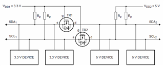
The level shifter has 2 transistors on each line. Guess the schematic is this (not 100% sure):
(EDIT: after checking, the level shifter board DOESN'T use this circuit. This circuit works fine with I2C and selfboot)
I2C communication between Arduino and adau1701 works fine through the level shifter, i can both write and read.
Now, before moving to a different level shifter (like TXS01xx from TI) do you have any idea why adau1701 doesn't selfboot?
Thank you a lot!
Omar
Edit Notes
after checking, the level shifter board DOESN'T use the depicted circuit. This circuit works fine with I2C and selfboot correctly.
[edited by: op-electronics at 5:36 PM (GMT 0) on 19 Dec 2019]
Audio Signal Processors
i2c
SigmaDSP Audio Processors
selfboot
adau1701
Hello Omar,
This is an interesting problem.
Level shifters can be difficult to deal with sometimes. The pull up values and the stray capacitance can be an issue.
So what are the resistor pull up values you are using?
Are the ones labeled in the diagram on the chip? If so then what values are they?
Have you looked at the transmissions on a scope? I would recommend doing that. This way you can see if one of the lines is stuck, or if the rise time is too slow.
Dave T
Hello Dave,
thanks for help. As pull-up resistors i have 10K both on adau1701 and level shifter. Tomorrow i will try to picture the circuit from level shifter board.
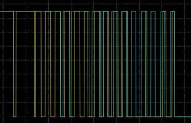
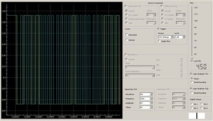
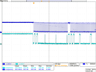
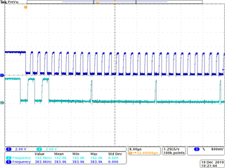
Here's the transmission on the scope immediately after power on of adau1701, looks like something is wrong there, but can't figure out what. After this both SDA and SCL go down for a while (probably the dsp pulling down the lines after failing to get aknowledges back?!):
This is a known good transmission between Arduino and adau1701 using same level shifter:
Let me know
Omar
I made a bidirectional level shifter from discrete parts using the circuit above and 10K pullup resistors and it now works! It does selfboot and can communicate over i2c.
So, the above circuit works fine and it's just the level shifter board i have which works with i2c but it prevents selfboot from eeprom.
Hello Omar,
For looking at these signals when you are having issues like this, a logic analyzer is only slightly helpful. It shows that there is communication happening and you can sometimes see the data values decoded but you cannot see the rise and fall times and what is going on the analog domain.
So use the analog inputs to a scope and see if you can notice anything.
We have 10K pull-ups on our eval board. Those are somewhat weak but this is because often it is connected to things like the USBi or a customer board that also has pull-ups. The USBi has 10K pull-ups so combined that is 5K which is a better value. That said, the eval board does boot up on its own with the 10K pull ups. We are not trying to write at the fastest I2C speed. Are you trying to boot at 400KHz clock speed?
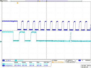
Here are some screenshots I just took of the MINIZ eval board booting up from EEPROM with no USBi connected. So only the 10K pull-ups.
In the above screenshot, you can see the start condition where the SDA went low when the SCL was high. You can also see where the DSP released the SDA line and it started to float up and then the EEPROM pulled it down before the next rising clock edge for the ACK.
You can see the risetime which is dictated by the pull-up resistors and the stray capacitance on the PCB and the parts that are connected to the bus. It is fast enough for the clock to reach a high and it has to stay high for the minimum setup time. If it does not then the clock pulse is missed. These are things you need to look for.
On the above screenshot you can see the next start condition.
In the above screenshot you can see several ACKs.
EDIT: I had the EEPROM and DSP ACK backwards. :)
Dave T
Please log in to reply.