ADSP-21479 SHARC processor SPI slave and full duplex mode failure.
Dear all:
My system is the ARM processor be master and 21479 sharc processor be slave, they communicate through SPI. Each time the ARM controller transfer data include transmit and receive, It run full-duplex mode. The parameters are set as follows: 500KHz buad rate, 8 bits per word, 0=clock phase, 0=clock polarity. So I refer to the ADSP-214XX SHARC Processor hardware reference and configure 21479 sharc processor running full duplex operation, this is the DMA channel to receive path and core access to transmit path. I think everything will be alright, as a result, there were some problems. I receive from ARM is right, but ARM receive from DSP is wrong, the testing result like this:
slave DSP : master ARM
receive: 0x55 0xaa 0x11 0x22 0x44 0x88 0xaa 0x55 transmit:0x55 0xaa 0x11 0x22 0x44 0x88 0xaa 0x55
transmit: 0x11, 0x12, 0x13, 0x14, 0x15, 0x16, 0x17, 0x18 receive:0x22 0x22 0x22 0x22 0x22 0x22 0x22 0x22
.......... .........
This is my test code :
/*
* spi_slave_transfer_test.c
*
* Created on:2019
* Author:evil
*/
#include<stdio.h>
#include <platform_include.h> /* System and IOP register bit and address definitions. */
#include <processor_include.h>
#include <services/int/adi_int.h> /* Interrupt Handler API header. */
#include <sru.h>
/*transmit and receive buffer definition.
* txBuf ---- transmit buffer.
* txCount ---- each transfer time transmit number data.
* rxBuf ---- receive buffer.
* rxCount ---- each transfer time receive number data.
*/
unsigned char txBuf[8] = {0x11, 0x12, 0x13, 0x14, 0x15, 0x16, 0x17, 0x18};
unsigned int txCount = 8;
unsigned char rxBuf[8] = {0};
unsigned int rxCount = 8;
static void init_spi_sru(void) {
/* ARM microprocessor and ADSP-21479 SPI routing:
* Master (ARM) Slave(ADSP-21479)
*
* CLK -----------------------> DPI_PIN08(CLK)
*
* MOSI -----------------------> DPI_PIN07(MOSI/RXSPI)
*
* MISO <----------------------- DPI_PIN06(MISO/TXSPI)
*
* CS -----------------------> DPI_PIN09(CS)
*/
SRU(DPI_PB07_O, SPIB_MOSI_I);
SRU(SPIB_MISO_O, DPI_PB06_I);
SRU(DPI_PB08_O, SPIB_CLK_I);
SRU(DPI_PB09_O, SPIB_DS_I);
SRU(LOW, DPI_PBEN07_I);
SRU(LOW, DPI_PB07_I);
SRU(HIGH, DPI_PBEN06_I);
//SRU(LOW, DPI_PB06_I);
SRU(LOW, DPI_PBEN08_I);
SRU(LOW, DPI_PB08_I);
SRU(LOW, DPI_PBEN09_I);
}
static void setup_spi_mode(void) {
/*
* transfer mode: CPHASE = 0, CLKPL = 0,WL = 0, MSBF = 1
* full duplex:TIMOD = 10, DMA channel to receive path,
* core access to transmit path.
*
*/
//setup
*pSPICTLB = (TXFLSH | RXFLSH);
*pSPIDMACB = FIFOFLSH;
*pSPISTATB = 0xff;
*pSPICTLB = SPIEN | MSBF | WL8 | TIMOD2;
*pIISPIB = (unsigned int)rxBuf;
*pIMSPIB = 1;
*pCSPIB = rxCount;
*pSPIDMACB = SPIDEN | INTEN | INTERR | SPIRCV ;
}
static void switch_receive_dma_to_receive_dma(void){
/*
* switch from receive DMA to receive DMA after each transfer,
* without disabling the SPI and DMA.
*/
*pSPIDMACB = FIFOFLSH;
*pSPISTATB = 0xff;
*pSPICTLB = SPIEN | MSBF | WL8 | TIMOD2;
*pSPIDMACB = SPIDEN |INTEN | INTERR | SPIRCV;
}
static void spi_transfer(uint32_t iid, void *handlerarg) {
/*
* write to the TXSPIB buffer during an active SPI receive DMA
* operation are permitted.
*/
//
for (int i = 0; i < txCount; i++) {
*(volatile int *)*pTXSPIB = (int)txBuf[i];
while((*pSPISTATB & TXS) != 0);
}
//print the receive data
printf("received: 0x%02x 0x%02x 0x%02x "
"0x%02x 0x%02x 0x%02x "
"0x%02x 0x%02x\n",
rxBuf[0], rxBuf[1], rxBuf[2],
rxBuf[3], rxBuf[4], rxBuf[5],
rxBuf[6], rxBuf[7]);
// switching from receive to a new receive DMA
switch_receive_dma_to_receive_dma();
}
/*
* Interface: outside to call function.
*/
void spi_slave_start_test(void) {
/*initialization SRU routing*/
init_spi_sru();
/*setup SPI mode*/
setup_spi_mode();
/* Install and enable a handler for the SPIB Receiver interrupt.*/
adi_int_InstallHandler(ADI_CID_P18I, spi_transfer, 0, true);
for (;;) {
asm("idle;");
}
}
I am looking forward to somebody can review it and help me, thank you very much!
Hi,
Sorry for the delay in response.
1) Can you share the SPIx status register values during slave transmission?
2) Can you share the block diagram with pull up/down resister used?
3) Please refer ez.analog.com/.../how-to-configure-adsp-21479-sharc-processor-in-spi-slave-mode
4) Can you try with SPI slave transmission alone first? During spi slave transmission, what is the value of DMA count register?
5) Please refer ADSP-21479 Hrm "DMA Buffer Status" at page no: 740 and "DMA Transfers" at page no:742.
Regards,
Anand Selvaraj.
Hi,
Sorry for the delay in response.
I am just running the SPI slave transmit alone in your advice, The testing code like this:/*****************************************************************************
* SPI_SLAVE_21479_TEST.c
*****************************************************************************/
#include <sys/platform.h>
#include <cdef21479.h>
#include <def21479.h>
#include <sru.h>
#include <services/int/adi_int.h> /* Interrupt Handler API header. */
#include "adi_initialize.h"
#include "SPI_SLAVE_21479_TEST.h"
#define N 10
int Source[N];
int Destination[N];
int DMA_Tx_done = 0;
int DMA_Rx_done = 0;
void SPI_Tx_Isr( uint32_t iid, void *handlerarg);
void SPI_Rx_Isr( uint32_t iid, void *handlerarg);
void InitSRU(void);
void main()
{
int i;
adi_initComponents();
for( i = 0; i < N; i++ )
{
Source[i] = 0x01 + i;
}
InitSRU();
adi_int_InstallHandler(ADI_CID_P18I,SPI_Tx_Isr,0,true);
*pSPICTLB = 0;
*pSPIFLGB = 0;
*pSPIDMACB = 0;
*pIISPIB = Source;
*pIMSPIB = 1;
*pCSPIB = N;
*pSPICTLB = WL8 | TIMOD2 | SPIEN | MSBF;
*pSPIDMACB = SPIDEN | INTEN | INTETC;
while(1)
{
asm("nop;");
}
}
void SPI_Tx_Isr( uint32_t iid, void *handlerarg)
{
DMA_Tx_done = 1;
}
void SPI_Rx_Isr( uint32_t iid, void *handlerarg)
{
DMA_Rx_done = 1;
}
void InitSRU(void)
{
SRU(DPI_PB07_O, SPIB_MOSI_I);
SRU(SPIB_MISO_O, DPI_PB06_I);
SRU(DPI_PB08_O, SPIB_CLK_I);
SRU(DPI_PB09_O, SPIB_DS_I);
SRU(HIGH, DPI_PBEN06_I); //Connect SPI_MISO_PBEN signal to DPI_PB06
SRU(LOW, DPI_PBEN09_I);
}
Each time I transmit the Source[10]={0x01,...,0x0A} to the host ARM controllor, but the ARM controllor only receive the last data 0x0A alone. The SPIB status register values is in the follow file, you can see it in the below。
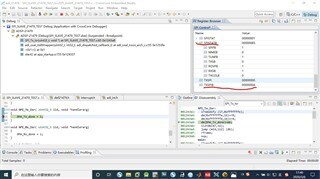
Additional information to explain each time the ARM controllor receive the data from DSP transmit like this:

Hi,
Sorry for the delay in response.
1) Can you check with it is working fine with Master transmitter(ARM) and Slave receiver(DSP) mode?
2) Can you share the probe signal for Slave transmitter mode?
3) Can you check with transferring data in core mode?
4) For slave mode the slave select pin (SPI_DS_I) needs to be asserted to start slave DMA operation.
5) Please refer ADSP-214xx Hrm "DMA transfers" in SPI chapter in the below link:
www.analog.com/.../ADSP-214xx_hwr_rev1.1.pdf
6) Are you using same SPI word length, mode and DMA configuration in ARM and ADSP-21479?
7) Can you check with any other SPI modes and reducing SPI clock?
Regards,
Anand Selvaraj.
Please log in to reply.