ADAU 1701 Rotary Encoder
Hi.
Having used the ADAU1701 on the SURE Electronics JAB3-50 board, I would like to implement a rotary encoder to my designs. However I don't seems to get it to work.
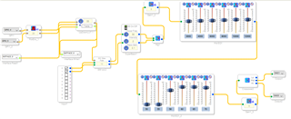
I have read the AN-951 on the subject, but there must be something I'm doing wrong, as there is absolutely no output when I upload the program to the processor. Here's my set up:
The programming is identical to the one in AN-951, and I'm using the GPIO 4 and 5 as they are the best available on the JAB3-50 board.
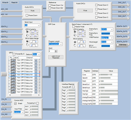
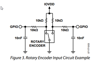
The hardware config is also showing the GPIO 4 and 5 to be assigned, and I have soldered up the described circuit:
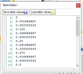
Also my Table should be correct:
Can anyone see where I'm doing something wrong, or perhaps direct me to a tutorial where things are explained a bit more "hands on"?
Best regards,
Peter
Audio Signal Processors
SigmaDSP Audio Processors
adau1701
Hello Peter,
I do not see what the problem is right away. It looks like you have it setup properly.
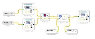
What I do not see in your project are tools that can help you troubleshoot and "see" what is going on inside the DSP. Place some readback cells to see what the DSP is reading from the GPIO inputs.
Place a readback to see what is coming out of the look up table. Place some meters in your project to see the audio level coming in and also going out. These are really great troubleshooting tools.
Here is an example:
Once you are done with development you can remove these to save some MIPS.
One other thing I noticed is that you need to place some DC Block filters right on the inputs of the DSP. ( the outputs of the ADCs) The ADCs do not have built in high pass filters so they will have a DC offset. Then when you send this through a filter in your project and the filter happens to boost low frequencies then you will boost this DC offset. It can also cause pops when switching.
So place these readbacks and see where the rotary encoder signal is failing.
Dave T
Hi Dave.
Thank you for the input. I'll try to investigate this and report back with result.
I'm a little in doubt how to use the read back blocks, but maybe that is self explanatory once I get them implemented.
BR
Peter
Came to think of that I'm using a "generic" RE... Do they have to be a certain type? Do they maybe come as a breakout board, ready to be insert with the ADAU1701 in JAB3-50? Are you familiar with the WONDOM JAB3-50?
Hello Peter298,
I have not used this board. I do see that they did bring out MP4 and 5 out to a connector. I could not find a schematic to check that it is not being used for anything else on the PCB that needs to be defeated. This is where an oscilloscope would be handy to see what the actual voltage levels are on the MP pins 4 and 5. By using the readbacks you can see if the MP port is actually changing. You simply click on "Read" and it shows you the value of the signal at that point in the DSP program. This is your "window" into the DSP and into the program at any point in the program. Keep in mind that the readback hardware in this processor is only a 24 bit number. So if you want to see the bottom four bits of the internal 28 bit number you will have to multiply by 4 twice to see it. This recent post I explain this more: https://ez.analog.com/dsp/sigmadsp/f/q-a/120935/adau1701-state-detection/359598#359598
Peter298 said:
Came to think of that I'm using a "generic" R
What are you saying is "generic"?
I suggest you attempt to contact Sure Electronics for more info and perhaps the schematics of the external MP pin circuits.
Dave T
By "generic" rotary encoder I mean one like this:
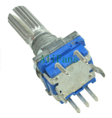
Hello Peter298,
I looked at the link from eBay. There is no datasheet.
You need to hook up an oscilloscope and see what type of output this encoder produces. Here is my experience on this subject.
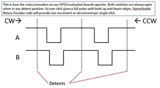
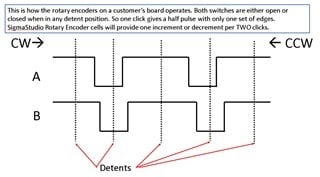
We had one customer have an issue with the encoder taking two clicks to change one step. I found the problem and I wrote a SigmaStudio program to translate the output of the encoder to what the encoder GUI wants to see. So look at your encoder and see what you get for outputs. Here are the details of what I was looking for:
This I will call type 1. (This is not any kind of standard name, just a name I made up for our discussion)
Type 2:
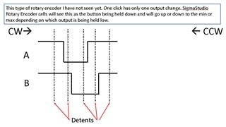
Last is Type 3 that I suspect you might have. I have not personally seen one like this but would explain your symptoms.
Let me know what you find once you have looked at this with a scope. You also can look at it using the readback cells. If it does change like this at each detent it will be easy to see from within SigmaStudio.
Dave T
Hi Dave.
Must say that I'm very impressed with the service you provide through this forum. The speed of reply is more than I would ever expect! Thanks.
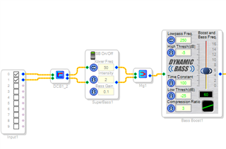
The DC Block filter are what block in the SS environment? EDIT: Never mind, I just found it... ;-)
Hello Peter298,
Yup! That is the one! It is really a must-use for this part unless you are going through a HPF in an application for other reasons. Then you would most likely not need it. All of our other parts with converters built in, or our ADCs, all have HPF built into the ADC but they did not do it on this part.
Let me know about the encoders when you get a chance. I am wondering if this is the issue.
Dave T
I see in your hardware config you didn't set the mp/gpio to no debounce . the debounce probably messes up the timing of the pulses from the rotary encoder. the example on the " GPIO Conditioning Examples" page doesn't mention to set them to no debounce but the page on the Rotary Encoder toolbox item does mention it. I must have lost a whole day because I missed this detail
you didn't set the GPIO/MP to no debounce in your hardware config . the debounce probably messes up the timing of the encoders pulses. I had the same problem and setting that made it work
Please log in to reply.