ADAU1466 strange problem with SPDIF -ASRC - two boards linking
Hello to All
We use ADAU1466 on our own developped board ( hifi product ). . Clock at 12.288 Mhz - Everything is working fine until now
Our program is including serial IN ( from ADC) and SPDIF input through ASRC . To make it short, these inputs are sent to serial out ( dac ) and spdif out ( from DSP) . The goal is to link several dsp board via SPDIF input-output . ( DSP is making some instructions before to output the SPDIF and before SERIAL output, thus we can not use the simple redirection option in routing matrix)
When we send a signal (from 1st board ) in the SPDIF input (2nd board) using this basic program , SPDIF INPUT locking is correct and output signal from DAC is stable .
But when we add some more instructions into this program, SPDIF INPUT locking becomes incorrect / unstable . ( it locks 1 or 2 seconds and lose it and relocks and lose it etc )
Kindly note we have the same problem if we change to Fs48KHz . We tried different setting for in the SPDIF hardware window but it didn't help .
The only way to get the 2nd board working correctly is to choose "spdif receiver" option into the "start pulse" option folder . (clock control window ) .
Thus it seems ASRC doesn't make the correct job . ( adding few instructions into the program is making the SPDIF and /or ASRC unstable --- a bit strange )
I hope to be clear enough in my explanations . ( programs are attached )
Any help and suggestion will be welcome .
Thanks a lot
Audio Signal Processors
SigmaDSP Audio Processors
adau1466
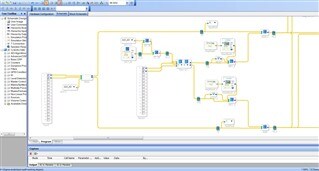
test-spdif.zip
The 2 files
Hello TH25,
I am looking into this... Thanks for sending the files.
Dave T
Hi. Are the programs that you uploaded running on the sending board, the receiving board, or both?
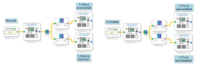
I've added a little instrumentation to your "not working" program. The left half checks the status of the Rx lock, and the right half checks the status of the Tx enable. Both seem well behaved for me. After letting it run for a while, I'm not seeing any loss of lock from an incoming S/PDIF stream or loss of the transmitter.
Would you please add this logic and confirm that the processor thinks you are losing lock on your hardware? The new blocks are Basic DSP > Logic > Toggle > One Shot Rise and One Shot Fall.
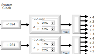
I did notice a separate issue with your project, though, that may or may not be related. I see that your project is set up to run at 96 kHz. The GUI is confusing, but the menu at the top only controls the graphical environment. To set the hardware to 96 kHz with a 12.288 MHz crystal, you need to change the clock divider in the CLOCK_CONTROL tab of the register window from 1/6 (48 kHz) to 2/6 or 1/3:
You will need to fix this, regardless, since your DAC is likely zero-padding between samples and every second sample from your ADC is likely being ignored. It seems unlikely, but perhaps this is related.
Ken
Dear Ken
Thank you very much for your detailed reply and suggestion
The program we sent are on the receiver board . ( sender is very simple program with 1 asrc input and 1 spdif out - no problem with it )
As to the 2nd issue you found, I think it is related to issue 1 but there is something which is not clear at all for us.
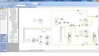
Of course, we adjusted "clock control" parameters according to the sampling frequency (96kHz) . you can see screen copy here .
But as you can see, if we want the signal (96kHz verified ) from SPDIF input is correctly proceed ( correct locking ) we must set the "start pulse" to base fs *2 . (in base fs, locking is failing ) . But in such case, it means the core and DAC are working in 192 k . ( since Start pulse is chosen @ *2 )
As you can see, we read paramater F582 (asrc ratio) and in this case , it shows 0.5
As you can see either we included your little instrumentation . In 2/6 with start pulse 2*fs , there is no locking lost . But if we chose 1*Fs instead , the "lock is ever lost" is showing 1 very quickly . ( We also monitor the F600 variable ... )
One question by the way, you said we must choose 2/6 instead of 1/6 . But what is the difference if we choose n/m at 1/6 , start pulse @ 2*FS and choose the 2*Fs option into the serial port configuration window ?
Thanks a lot in advance

Hello Dave . Have you seen something wrong on your side ?
The SigmaDSP family are, for the most part, stream processors. This means that the algorithm executes completely once per sample period. If you are doing block processing, that is done in the "leftover" time. START_PULSE sets the interrupt source that tells the processor to begin computing the next sample frame. In essence, this is what sets the core's sample rate. In the majority of application, the source for START_PULSE is Base_Fs, corresponding to the rate of CLKGEN1 x1. This default setting works for most people, but not here.
If I understand correctly, you would like to lock the entire processor to the recovered rate of the incoming S/PDIF signal. This is possible, but it takes some setup as follows:
On the CLOCK_CONTROL tab:
START_PULSE = S/PDIF receiver rate
CLKGEN3 N = 1024
CLKGEN3 SRC = Locks on FREF, needs N
FREF source = FREF comes from S/PDIF receiver
On the ROUTING_MATRIX tab:
ASRC0 Source = From S/PDIF receiver
ASRC0 Output rate = Use DSP rate
SPDIF Tx = From DSP
On the SPDIF tab:
SPDIF TX EN = Enabled
SPDIF Rx and Tx MCLKSPEED = SYSCLK
SPDIF RESTART = Enabled (green)
An example project with these settings is attached, but I'll walk you through.
START_PULSE is set to the S/PDIF receiver rate forcing the core's sample rate to be equal to the recovered clock. CLKGEN3 is configured to track this same rate by way of FREF. The S/PDIF signal comes in through ASRC0. However, by setting the output rate of the ASRC to Use DSP rate, you are forcing it to track START_PULSE, which is the same rate. Therefore, the ASRC ratio is locked at 1, and it is not really doing any sample rate conversion. The S/PDIF transmitter is also set to output at the DSP rate so the Tx and Rx rate are the same. The S/PDIF transmitted must be manually enabled, and setting the MCLKSPEED to SYSCLK allows is to run up to 192 kHz if need be and gives more headroom around 96 kHz.
The second piece of the puzzle is mixing in an I2S stream from an ADC. If the DSP is the clock master (the ADC is the clock slave), then the SPORT should be set to:
Sampling rate = Fs
Clock Generator = Clock generator 3
BCLK/LRCLK source = master
This will run the serial port at the same base Fs as the core, which is locked to the S/PDIF input rate. If the ADC needs to be a clock master, you will need to use another ASRC, but the sampling rate should still be set to Fs. If the rate is set to Fs*2, you will just be repeating samples on the output.
Lastly, you should be aware of some idiosyncrasies of the S/PDIF receiver. The first is that the ASRC outputs a DC value until it is able to lock on the input clock. It is a very good idea to check the lock status bit manually and mute when it is not locked. I've included an example showing this, as well. It's written for the ADAU1452, but it works identically.
Ken
ADAU1466-Lock-All-to-SPDIF-Input.zip
ADAU1452-ASRC-Lock-Detect-Example.zip
Dear Ken
Thanks a lot for your detailed answer.
Ken.M said:
If I understand correctly, you would like to lock the entire processor to the recovered rate of the incoming S/PDIF signal. This is possible, but it takes some setup as follows:
No , we don't want this .
My explanation is certainly badly conveyed. I am sorry . Actually, we don't want to lock the core according the spdif input ........ I just said if we use this option into the program I attached previously , we succeed to get a stable signal from spdif . Just try to give you some more information on what we tested . But so far , we want to use regular way with core timing reference ..... Thus using ASRC for it normal job ! and this is where we have problem ... :-(
Th.
OK. Please list all of the inputs and outputs, the sample rate for each, and which are clock master/slave. I'll walk you through setup.
Ken
In order to avoid any problem we setup the GEN1 to 2/6 as you said. Start pulse to BASE FS
The serial input and ouput ports are set on BASE FS and CLOCK GEN1
We have SPDIF input (we can provide signal in it at 96 kHz or 48 or 44 ) .
ASRC 0 is set to SPDIF receiver ( and use DSP rate)
We have no problem for analog in . ADC , DSP and DAC are working correctly
We have problem with SPDIF input . It seems the ASRC is not doing it job correctly when program is medium to bi sized . ( if program is very small , it works and this where it is strange )
If I insert this into your project above called test-spdif-notworking,dsproj, it correctly reads 1 when I give it 96 kHz over S/PDIF and 0.5 when I give it 48 kHz. Is it doing this on your hardware?
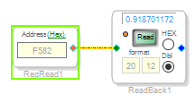
We tried the "internal Fs" ... unfortunatey it doesn't change anything on this problem
.
F582 is changing when we change source rate .
( I think the ASRC is working a very short time , thus it can detect the incoming rate )
I'm sorry. I can't imaging why the ASRC would suddenly stop working. Can you send your latest project with all of these changes? Now everything is working, but it is losing lock on the SPDIF or on the ASRC?
We will prepare the updated file to you .
With short program it doesn't loose anything . With longer program it looses both and we can see the F600 parameter which is swinging continiously from 1 to 0 0 to 1 and quite fastly .
By they way, we verified power supply on hardware and it is stable ( one could think the voltage can drop with big program and could affect spdif input behaviour ).
Hi Ken,
I am the designer of the hardware using the ADAU1466.
First of all, thank you for your support.
I will try to describe the configuration and problem encountered.
The DSP is the heart of a processing board with 2ch ADC, 4 ch DAC, 1 coaxial SPDIF in, 1 coaxial SPDIF out.
On a clock level, the DSP is the master : it provides MCLK to the chips through CLKOUT, as well as the BCLK and the LRCLK of the serial interfaces.
We have no problem converting analog signals through the ADC and playing them out through the DAC.
We tested 48ksps, 96ksps and 192ksps, and finally selected 96ksps.
For that, we set CLKGEN1 to 48kHz (N=1 and M=6), START PULSE at 2xFs, serial ports at 2xFs.
Even with big programs, if we stay below 3000 instructions per cycle, everything is fine.
But when using the SPDIF input, thing are completely different.
We of course use an ASRC to adapt the incoming frequency to the DSP's core frequency.
And here the mystery begins: it seems that the SPDIF receiver loses lock depending on the program!
Like TH25 explained above, small programs (i.e. schematic) work, bigger ones fail.
Having gone through all registers setting testing, we are a bit lost.
Remains 'hardware' possibilities, like:
- noise on the power supplies? AVDD?
- PLL filter problems?
- jitter on the sysclk?
- SPDIF input electrical problems?
- link with current consumption depending on program size?
- bad digital PLL for SPDIF clock recovery?
- bug in the silicon?
- interferences between core and SPDIF receiver?
Power supplies look good.
We are not using an optical SPDIF receiver, but a Coaxial connector with isolation transformer.
We have around 500mV peak to peak on the input (200mV minimum recommended).
We even increased to 1V, without success.
Have you done tests with coaxial SPDIF interfaces?
Do you have a recommended input schematic?
On the 'software' side, is there a possible link between the SPDIF receiver and the program? Or the ASRC?
Are they dedicated hardware blocks, or do they need some software?
Is there some interrupt mechanism between them?
How does the SPDIF digital PLL works?
As you can see, many questions, but still no answers :-(
And the boards will soon be manufactured, so we need to be sure it is not a hardware problem.
Again, thank you for your help.
Raph, thanks a lot for your very clear inputs
Raph said:
Even with big programs, if we stay below 3000 instructions per cycle, everything is fine.
This should have been the first thing that I asked.
At 96 kHz, the core is only capable of running 3022 instructions. Does this match your experience?
I have not, personally, designed a circuit with a coaxial S/PDIF interface, but I have seen many options on the Internet.
Ken

As I wrote, we are far below the 3000 instructions limit.
So this is not the reason.
The SPDIF input is not electrically specified.
So it is difficult to know the input impedance, capacitance,...
But we satisfy the capacitive coupling as well as the 200mVp-p requirements.
I would really appreciate to have a recommended schematic for coaxial SPDIF.
This morning, we had some strange behaviour with the ASRC.
96ksps SPDIF input to 48ksps core rate worked.
But 96ksps SPDIF input to 96ksps core rate did not.
And that is precisely what we need (because of the frequency difference between 2 devices).
Any reason why the ASRC will not work with a ratio close to 1???
I apologize. I thought you were saying that the system is working only if you stay under 3000 instructions.
The electrical specifications for the S/PDIF input pin are the same as all of the other digital inputs and are specified in the datasheet.
The ASRC is specified to work with a ratio very close to unity. That is a very common use case.
I've contacted you by email. Let's take this offline, and I'll post the solution when we sort it out.
Ken
Dear Ken
Thanks in advance to keep me in the loop by mail
Th
Please log in to reply.