EVAL-ADAU1787Z DMIC Inputs Not Connected
ADI,
Are you aware that the DMIC Clock and Data lines on J6 and J7 are unconnected on the EVAL-ADAU1787Z? Is there a reason for this? Seems to me like these should be connected... Are there any other bugs with this board I should be aware of?
Best,
Trey
ADAU1787
Integrated/Special Purpose A/D Converters
SigmaDSP
eval-adau1787
Audio CODECs
Hi Trey,
The connectors you are pointing to were provided for another DMIC EVAL board which ADI had. That DMIC part and EVB's are discontinued from ADI and no longer available. Hence the J6/J7 are not wired on the ADAU1787 board. We need to take them off from the board. I will update the BOM and schematic.
However for the DMIC connections, the J5 header is provided. These should be used. See the picture attached. It can be used to connect upto 4 DMIC's.
There are no other known limitations on the EVB.
Regards
Rajeev
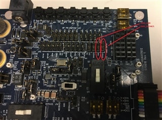
I'm fully aware of the J5 connector and have jumpered that over to the J6 and J7 connectors. Instead of removing them, perhaps you should simply connect the clock and data lines over to them? I think they are very useful because they provide power and ground for external mics as well as pulls for the polarity lines.
Perhaps you could also document this issue in the eval board user's guide so customers have a better user experience when evaluating this board?
Best,
Trey
I just hit this, and opened my own issue before I found this one.
I would strongly second Trey's take on this - the schematic, silkscreen, and connectors are all very misleading to users. Leaving these kinds of tripwires hanging around is really not at a level of professional polish appropriate for a $400 eval kit...
Agree - please update the documentation and if you need to update the PCB at some point in time then please connect to J6 and J7.
Please log in to reply.