ADAU1452 spi slave mode : datasheet says mode 3 but USBi actually uses mode 0
Really two questions:
1. How is it that is works with either mode without (non existent) re-configuration?
It looks like all the data will be shifted by 1 bit if you use the wrong mode.
But it seems to work fine.
2. Why does the official Analog Devices USBi use the wrong mode!
Audio Signal Processors
adau1452
spi
usbi
SigmaDSP Audio Processors
i think they just loosen up the timing so it works.
I did an implementation using mode 3 with an STM32F1 MCU.
Hello,
You have discovered that the ADAU1452 datasheet declares the SPI slave interface as Mode 3, and yet the USBi uses SPI Mode 0. Both statements are correct. The ADAU1452 ignores the leading and trailing falling edges of SCLK, so both Mode 0 and Mode 3 masters will work with the ADAU1452 slave port.
Microcontroller interfaces should work fine over both Mode 0 and Mode 3. If it's a simple library initialization call to switch between them, you might as well use Mode 3, since the datasheet defines the interface that way.
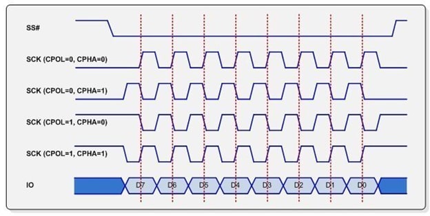
The following image from https://www.corelis.com/education/tutorials/spi-tutorial/ may help clear things up.
The difference between SPI Mode 0 (CPOL=0, CPHA=0) and SPI Mode 3 (CPOL=1, CPHA=1) is a half-cycle shift in SCLK. The DSP does not care about the first SCLK falling edge shown in Mode 3, or about the final SCLK falling edge in Mode 0. Since the protocols are otherwise identical data is transferred properly in both directions under both setups.
SPI modes 1 and 2, however, will NOT work with the ADAU1452 slave port because outgoing data is read on the falling edge of SCLK instead of the rising edge.
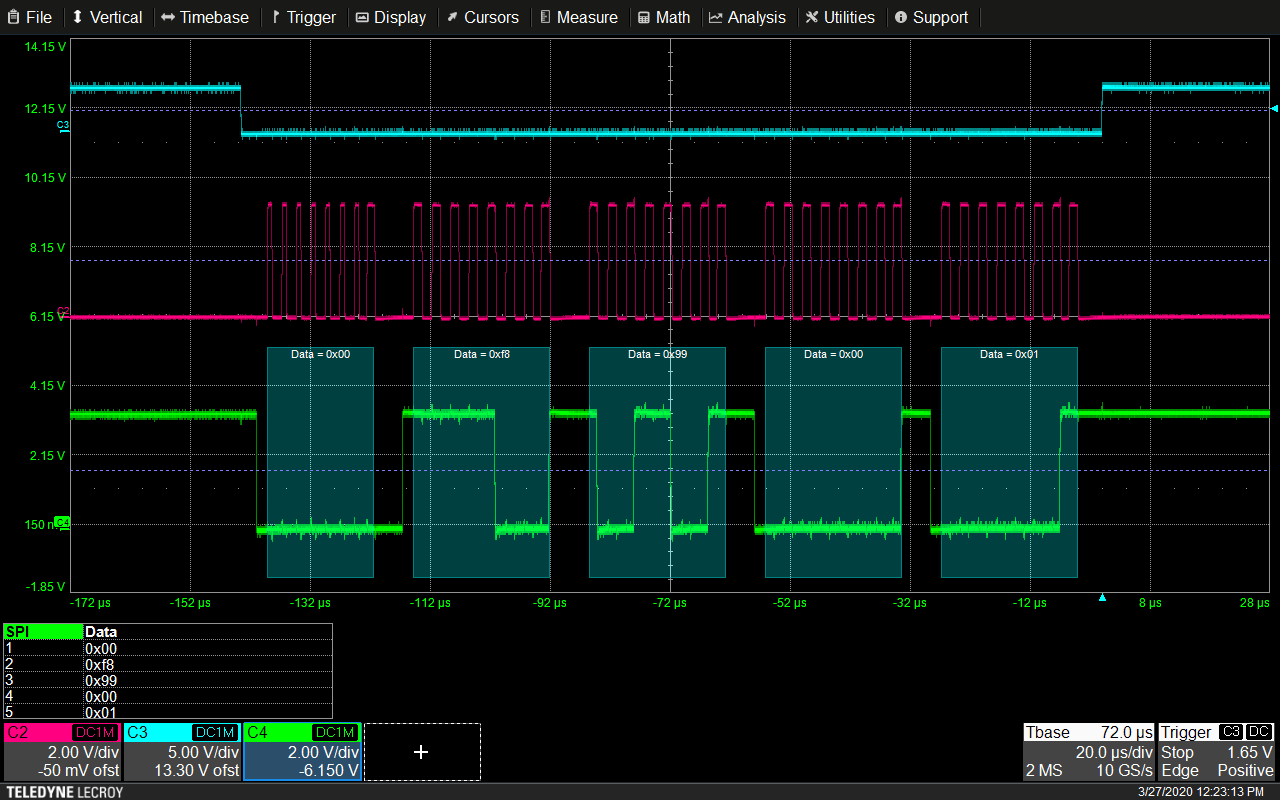
This scope capture shows an SPI data packet being transferred from the USBi to the DSP. You can see that when /SS is pulled low, SCLK is low, and the first rising edge of SCLK corresponds to the first valid data bit. This confirms your finding that the USBi must be using SPI Mode 0.
By the way, I didn’t notice that the USBi uses SPI Mode 0 until now. Good find!
Joshua
This is exactly a critical point : USBi MODE 0 DOES NOT WORK PROPERLY WITH SIGMADSP:
we discovered on an official 1452 Evaluation bard that putting some little wires in parallel with the SPI lines , like with a salae logo analyzer, this add some parasitic capacitance which destroy the timing and then you can't reliably program or R/W in the device.
We made a prototype with 2 Sigmadsp on the same SPI bus and were unable to use the USBi , this looks us several days to realize this problem.
Using a Microcontroler with proper SPI mode 3 did solve every thing!
Hello,
I think the issue here is signal integrity, NOT the SPI mode.
The USBi has 1k resistors on all the data lines for protection. This is not a problem with one slave board connected, but as the load becomes harder to drive, the data can be corrupted. You might try removing those resistors on the USBi and see if the problem goes away. But then there will be less protection on those data lines.
You can also try using Mode 0 on the microcontroller; you should find that this works without an issue. I've used both Mode 0 and Mode 3 without a problem.
Thank you, Joshua. I have been having reliability issues with the USBi on the EVAL boards from Analog Devices, and I finally attached a logic analyzer to try and find out why. So far, the data is correct, but SCLK shows Mode 0 from the USBi, not Mode 3.
I am impressed that ADI EngineerZone found this thread when I tried to write up the inconsistency between the data sheet and the recommended tool.
Please log in to reply.