ADAU1463/ADAU1467 Power Supply Design
Hello all,
I'm starting the hardware design for the ADAU1467, and I have a few questions:
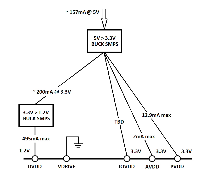
First Question - I plan to use 5V main power supply, and I plan to minimize current consumption to minimum as much as I can. To do so, I plan to use switch mode power supplies (unlike the evaluation board that both 3.3V, and 1,2V rails are supplied using LDOs)
Is the following power supply design is acceptable? (any suggestions for how to improve the design would be welcomed)
Second Question - Are there any software configurations that needs to be set when using external 1.2V supply, as above?
Many thanks!
Nir
Audio Signal Processors
adau1467
SigmaDSP Audio Processors
Hello Nir,
This all looks good. The only thing I think you should consider is to provide extra filtering for the PVDD power supply. This supplies the PLL so the power needs to be clean and free of switching noise.
The IOVDD as you show is TBD. This is a variable that depends on how you do the clocking, the sampling rate and the parts that are interfaced with the DSP. We did put some numbers in the datasheet for an idea of what it might draw but it is dependent on the details of your design.
The load on the DVDD varies at the rate of the sample rate and the instructions being executed. So you may need some filtering and check on the stability of the switching supply. Are you using our power products? The power group can help you with those details.
Dave T
Hi Dave,
Thanks for your reply,
I should have mentioned it, this is a simplified schematic, and additional filtering (ferrite beads etc...) will of course be added.
You have mentioned the PVDD power supply being sensitive to noise, and that gave me an idea how to improve my power supply design.
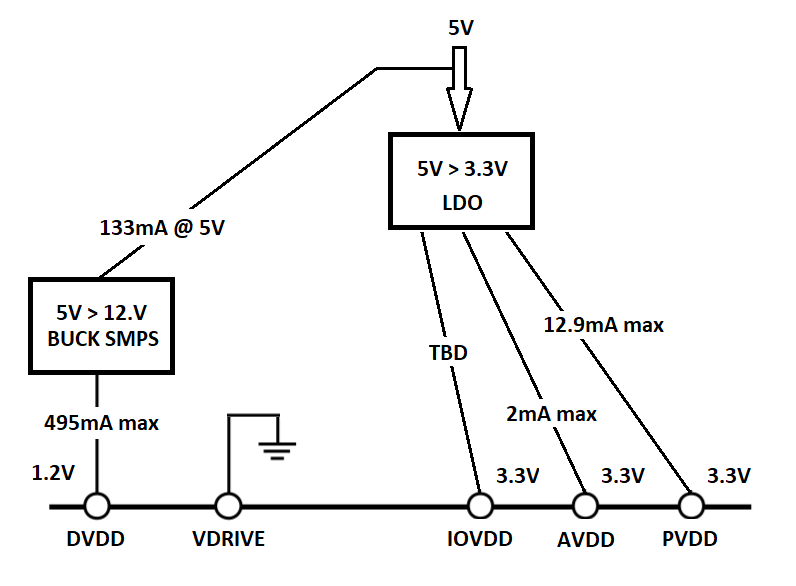
The PVDD, AVDD and VDDIO have relatively low current consumption (In my case, I estimate no more than 50mA for all three supplies), so I will create the 3.3V supplies using a LDO instead of a SMPS, like so:
This way I can avoid switching noise in PVDD, and still maintain good efficiency.
So, thank you for that comment
I asked an additional question regarding any software definitions that may required when using external 1.2V, so are there any?
Thanks again,
Nir
Hello Nir,
There are no registers associated with the internal linear regulator circuit. The DSP code does not change if you would like to use an external 1.2V supply for DVDD instead of the internal regulator circuit.
Joshua
Hi Joshua,
OK, great!
Thanks again,
Nir
Hello Nir,
My concern with the change you made from the earlier system is that timing of the DVDD cannot be before the IOVDD. Most switching supplies have an enable pin that will keep the output off until it is signaled to turn on. This should be driven by the IOVDD supply so that you can guarantee that the IOVDD is up before the DVDD is up. In your old setup that was guaranteed so I did not mention it.
Dave T
Hi Dave,
No problem, I will tie the SMPS enable pin to the LDO 3.3V output, or "power good" pin.
Thanks!
Nir
Please log in to reply.