ADAU1463/67 datasheet errors?
I am referring datasheet Rev. A. Kindly point me to an updated version, if any.
I was looking into the Serial Control Port sections and found the description to be confusing.
On pg. 36, it says 'A total of four control ports are available: two slave ports and two master ports.'
I could locate only three serial control ports as given below
As per the fig. 11: Pin Configuration on page 18 has the following (Referencing I2C port pins only and assuming selfboot using I2C EEPROM):
Pin 30: SCL2_M, Pin 31: SDA2_M. Is this I2C master control port 2?
Pin 34: SCL_M, Pin 35: SDA_M. Is this master control port 1?
Pin 38: SDA, Pin 39: SCL: Is this slave control port?
Fig. 11 denotes pin 42 as selfboot. However its description on pg. 20 has a typo and references pin 37, instead of pin 42. I hope I am correct.
So if connection of pin 42 to IOVDD initiates selfboot operation, then to which of the two master I2C ports can I connect the selfboot EEPROM? Pin30-31 or Pin 34-35?
In addition to pin 42, do I need to (as per description of pin 32 pn pg. 20) connect pin 32 to DGND through 10K resistor for selfboot operation using I2C EEPROM?
Thanks in advance!
Hello,
Datasheet Rev. A is the most current version.
The four interfaces available on the ADAU1463/1467 are as follows:
I2C Slave Port (pins 38, 39)
SPI Slave Port (pins 38, 39, 40, 41)
I2C Master Port (pins 34 and 35, default; pins 30 and 31, secondary)
SPI Master Port (pins 32, 33, 34, 35)
As you can see, the I2C and SPI interfaces are multiplexed. Pins 34 and 35 are used for both the I2C and SPI master ports. To offer additional flexibility the ADAU1463/1467 allow you to reassign the I2C bus to Pins 30 and 31. This would allow you to, for example, boot from an SPI EEPROM and then use the DSP to configure a CODEC over I2C, while keeping the interfaces electrically separate.
To use an I2C EEPROM you should use the PRIMARY interface for the I2C master port, on Pins 34 and 35. Since the DSP is using the EEPROM to boot itself there is no way for the DSP to switch its interface to the secondary master port ahead of time.
Please refer to Page 45 on the ADAU1463/1467 datasheet for more information on required configurations for self boot. Briefly, the SELFBOOT pin (42) must be at logic high and the SS_M pin (pin 32) is tied low through a 10k resistor for an I2C self boot.
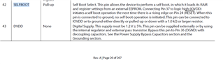
I cannot find the typo you referenced on Page 20. I am seeing Pin 42 in my screenshot below, which matches the pin configuration in Figure 11, and this is correct. Am I looking at the right location?
Please let me know if I can clarify any of this further.
Joshua
Hello,
Thank you for the reply.
The multiplexing of the I2C and SPI pins was clear to me. But I could not gather from the datasheet that there was a primary master port and a secondary master port and that we need to connect the selfboot EEPROM to the primary master port. Configuration details related to self EEPROM is clear to me now after reading your reply. Thanks!
Earlier sigmadsp chips had both SPI/ I2C control ports but used I2C interface as an example. With the recent chips, the SPI is used on eval boards. Any specific reason for this shift? Ease of large memory interface, maybe?
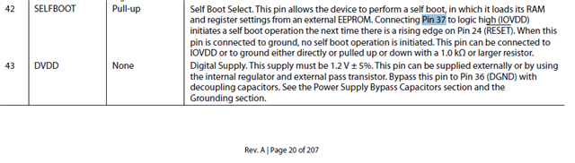
For the typo check the description for pin 42. It seems to refer to pin 37 as selfboot pin. But the intent was to tell to connect pin 42 to pin 37.
Another typo is in the description of pin 31, being referred to as '(SCL2_M)' instead of '(SDA2_M).'
I am starting to populate my schematic and may come back for more clarity on other blocks, if needed.
Thanks again!!
Hello,
I see what you mean about Pin 31. You are correct, the highlighted "SCL2_M" text below should read "SDA2_M".
And, the highlighted "Pin 37" text below should read "Pin 42".
Recent SigmaDSP interfaces shifted from I2C to SPI because of the higher throughput when using SPI.
Both I2C and SPI are valid interfaces on all of these processors; if you are using a microcontroller to program the DSP, one interface might make more sense for your particular implementation.
Joshua

Hello,
Just to cross confirm: One needs to connect the selfboot EEPROM to Primary master port and additional slave device like a CODEC to secondary master port.
For the ADAU1467, what is the largest EEPROM size required in a worst case memory intensive application?
When using I2C selfboot EEPROM, does 512kb become a limit that the DSP can access? If yes, will this be a restriction when using I2C selfboot EEPROM without a uC?
When using SPI selfboot EEPROM, does 64MB become a limit that the DSP can access?
Thanks!!
Hello,
The EEPROM must be connected to the primary master port, on Pins 32-35. This is true for both I2C and SPI devices. Additionally, for I2C self boot, the SS_M/MP0 pin should be pulled low by a 10kΩ resistor (see p. 20 of datasheet).
For other devices on the master port there are a lot of valid configurations. How they should be set up depends on your implementation. For example, all of the following are valid configurations, and there are certainly more. Often there isn't a single right answer and multiple setups can work.
I2C EEPROM on the primary master port, I2C CODEC also on the primary master port (if I2C addresses are unique)
I2C EEPROM on the primary master port, I2C CODEC on the secondary master port (regardless of I2C address)
I2C EEPROM on the primary master port, external I2C address expander on the primary master port, multiple identical I2C devices fanning out from the address expander
SPI EEPROM on the primary master port, I2C CODEC on the secondary master port
SPI EEPROM and SPI CODEC both on the master port, as long as slave select lines are separated
SPI EEPROM and up to 7 identical SPI CODECs on the master port as long as slave select lines are separated, this depends on how many MP pins are available
Keep in mind that register writes for these devices will end up being stored in the EEPROM alongside your program data. This limits the maximum size of your DSP program, sometimes enough that it makes sense to add a microcontroller to the system.
As for the memory size, this depends greatly on your specific application.
The ADAU1463 has 48 kWords of data memory and 16 kWords of program memory. This adds up to 64 kWords. Each word is 32 bits long. This corresponds to a maximum memory depth of 2.048Mbit. This does not include the register data which also needs to be stored. Registers which stay at their default values do not need to be re-written.
The ADAU1467 has 80 kWords of data memory and 24 kWords of program memory. This adds up to 104kWords. Each word is again 32 bits long. This is 3.328 Mbit. Again there is register data on top of this.
For both devices there is also the EEPROM header and some framing, described on p. 45 of the datasheet, which will require some additional overhead.
This is assuming that you fill every last bit of the DSP program and data memory, which usually is not the case.
If your program is small, you can use an EEPROM with less memory. Usually multiple memory sizes are available in the same footprint so your first prototype could have a very large EEPROM and once you know the size of the program you can switch to a smaller device.
Lastly, SPI EEPROMs will allow the DSP to boot faster, which is important for many applications.
Joshua
Thank you for the details.
I will post my doubts related to self boot in my other thread here: ez.analog.com/.../need-hints-on-use-of-two-control-ports-on-advanced-sigmadsp-processors
Please log in to reply.