Up/Down Accumulator in ADAU1701
Hi,
Apart from making a couple of relatively easy projects where I was able to find plenty of examples to get me through, my knowledge of DSP is close to zero but hope to learn, so please bear with me and no doubt my stupid mistakes!
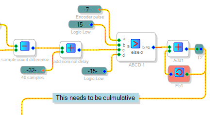
The current challenge requires what I'll refer to as an accumulator which will hold the delay tap value for a Voltage Controlled Delay block. The objective is to vary the delay based on an external clock signal from a rotary encoder. I count the number of samplerate samples between rotary encoder pulses, compare to the expected reference value and then wish to increase or decrease the delay depending on the calculated difference. The actual values are roughly 180 samples at 96kHz between encoder pulses and for any given measuring period the difference will be small, probably in single digits. Where I'm stuck is how to make this difference cumulative. It will be the case that the average over time will be the reference value.
The overall min and max limits will be around +/-40 samples so I have a VCD block with max set to 80 and with the nominal value set at 40. Have attached my test project for where I'm currently at, a note shows where I would like the cumulative value rather than the per measuring period value which it currently has.
Hope it makes some kind of sense and would appreciate some help to resolve this, or in fact any better ideas to achieve my goal, which is to provide live wow and flutter removal for a special transport system where the average speed will be accurate, but will have up to +/- 20% variances.
Thank you in advance,
Frank
PAtest1.zip
Audio Signal Processors
SigmaDSP Audio Processors
adau1701
Hello Frank,
You've got quite an interesting application. From your description it sounds like you need to accumulate your error signal from one encoder pulse to the next. To do this, add three blocks to your project -- a ABCD Comparator, a Feedback, and an adder. A Signal Add block with feedback from its output to one of its inputs adds to itself -- for example, you can make an integrator this way. I'm assuming that your application calls for accumulating the new measurement just once per encoder pulse as opposed to 96000 times / second (which would cause a runaway accumulation). This is where the ABCD Comparator comes in -- we can have it allow the measurement into the accumulator just one time per encoder pulse.
As you're finding out, you can do some amazing things with SigmaDSP which go beyond ordinary audio post-processing.
Best regards,
Bob
PAtest2.zip
Hello Bob,
Many thanks for your reply and solution to the accumulator. I made a mistake in where I placed my cumulative note, it should have been before the 40 sample offset for nominal delay of course.
Have been working on it most of the day and made some progress, but not yet working. I added a manual reset for now in the accumulator feedback and used it to set the 40 sample nominal delay offset, gating the effect of the switch to only work when the error difference is zero - well at least this is my intention, but maybe I'm still misunderstanding things! Latest version attached.
Thought it worth some time to generate a more representative test signal, so in with Oscillator, VCO and Value Cross Detector blocks to generate an "encoder" pulse with a 25Hz wobble on it. Also used the VCO output as a test audio source as by definition the encoder pulse period variations should mirror the audio wow and flutter. If can get the test tone output to have no wobble then that's half the job done!
I need to keep going at it but just wanted to respond now to say thanks, no doubt I'll be asking for help again soon!
Best regards,
Frank
PAtest3.zip
Hi Frank,
Glad to hear you're making progress and that you've found my suggestion helpful. I understand what you're doing with the two Logic Gates to build your Zero Offset detector:
This should output a zero value to reset your accumulator when the offset is exactly zero (although I'm figuring you want a NAND at Logic2, since the AND shown does nothing) . However, it's quite possible for the offset to pass right through zero without ever being zero. For example, going from -1 to +1. Welcome to the discrete nature of DSP! If you wish the accumulator to reset every time the offset finds zero, you can use the Value Cross Detector instead. This outputs a "high" pulse each time its input crosses the value you set in its box (of course leave this at zero). To invert the logic you could use a NAND, yet I'd recommend a Zero Comparator. This outputs a selectable value only when its input is zero. Selecting "Bit 23" outputs 1.0 decimal, but you can select any output since you're comparing this to zero in the ABCD Comparator. Hope this helps.
Best regards,
Bob

Hi Bob,
Thanks again. That second gate should have been a NOR as an invertor - I dragged into onto the schematic and forgot to change it from the default AND.
This part is a quick and dirty to manually reset the count back to the nominal but yes, I take your point about it could take a while (if ever!) to actually be zero. In final use, I would not be doing this manually and it can't happen each time the difference is zero because there may be a lop-sided cumulative error whereby the difference needs to change polarity to gradually bring it back to the nominal value. The reset is more of a "ok, start stabilising from here on" instruction.
In the final application, the transport set point speed can be changed and hence the reference value will have to change accordingly. Also, although the mechanical guy says the transport will be stable on average, I cannot believe any absolute value will not creep - even a couple of crystals will creep relative to each other over time. To resolve this, I'm thinking I will need a longer term count to modify the reference set point to account for a drift in the average - not thought about how I'll do that yet! Might be easier in a microcontroller.
At this stage I'm just testing an idea with this variable delay concept. There is a current microcontroller solution where the audio is sampled at fixed rate and then a live resampling is happening by a ratio determined by the sample count difference between encoder pulses. But the heavy lifting for that solution is in the PC, I'm hoping to provide a solution at the board level.
Best regards,
Frank
EDIT: Corrected gate name errors
Hi Bob,
I had trouble getting it working and had to park it to one side for a while. Got back to it today and narrowed down to a problem I do not understand, so would appreciate some help please.
Have divided up the schematic into blocks with comments and named aliases to hope make it clearer as to what should be happening. I'm stuck with the difference block: With the VCO "wow and flutter" modulation off, the simulated encoder pulses will always be 0xB0 samples long and if I inspect the value at Count value (alias 26) via INTFACE_5 it does indeed seem to always be this value and hence when compared to the Ref Count (alias 20) I would expect the Difference block output (alias 25) to always be zero. Whenever I read INTFACE_0 it shows solidly at zero. After the block which should only pass the value during the encoder pulse it should also be zero and INTFACE_1 again solidly reads zero but the Accumulator block keeps incrementing. If I throw the Test switch (Nx1-4) to a DC block zero value then the accumulator does not increment. So this is the dilemma, sample count difference (alias 25) should be zero and reads as zero, but does not behave as zero compared to a zero from the DC block. I'm clearly misunderstanding something, but not yet figured out what!
On a different point, to help debug I've ended up using writes to registers with manual reads in SigmaStudio. Is there a better way to do this? I tried DSPReadback but it throws away the last nibble, so not a lot of use. EDIT: Just had a thought, I guess I could put in a 16x multiplier before the DSPReadback.
Best regards,
Frank
PAtest5.zip
Update: I added an option to supply the reference value further back in the chain instead of the Sample count value from the timer and the accumulator does not increment. I think the problem is somewhere in the count and hold area, will keep investigating.
Best regards,
Frank
Hello Frank,
I experimented with the PAtest5 project for several hours this morning. I like how neat you've made it. Yes, the accumulator keeps incrementing as you described. Evidently there must be some fleeting (intermittent) non-zero values coming from the Difference block, even though the Interface reads consistently zero. I've got several thoughts for what they're worth:
You could catch any non-zero pulses from the difference block by temporarily routing this point to a DAC and then scoping the resulting signal. Because the difference signal is likely to be just a tiny integer, multiply it with cascaded gain blocks until it's big enough to see this way. Also the -1701's DACs invert the signal.
Calculations predict a count of 176.98 per encoder pulse. Thus there's a small positive bias from the difference block which could accumulate (but I don't know if the fractional part matters since we're dealing with integers here). Now, if the average drive speed can be counted on to be accurate, do we really need the system's feedback loop to work down to DC? AC coupling the loop can still minimize the (AC) wow and flutter while preventing the accumulating error.
The counting method gives an eight-bit measurement (about 176 / 255). it may be advantageous to make use of more of the available 28-bit resolution.
Perhaps an alternative scheme which directly measures the encoder frequency would provide more stable results. Here's an example from a similar application. Hopefully its bandwidth could be increased sufficiently for your application.
Best regards,
Bob
Hi Bob,
Many thanks indeed for all your time on this and valuable thoughts/suggestions. I like your idea to go with a frequency measurement approach and have taken a look at and a play with the example you linked to.
Some points so far:
I added the Hysteresis comparator in place of just the value cross detector although I'm not sure it improves jitter. At 48kHz sample rate there is a regular one sample pulse jitter. Interestingly, at 96kHz this seems to disappear. Anyway, this will probably not be needed for real encoder pulses and these will jitter anyway by definition especially as they will be asynchronous to the DSP clock. They should be only one sample pulse wide out of the rotary detector so already suitable for the F -> V converter.
To run correctly at 96kHz I had to double the two filter frequencies in the F -> V detector to 20Hz, otherwise the output VCO in the example jittered really badly.
The next stage I will need to work on is converting this detected value into a suitable index for the Variable delay block. I guess adding the output of the detector to some DC offset to nominally sit it in the middle of the delay block range, with suitable scaling of course. Probably makes sense to AC couple (use a DC block) the detector output before adding it to DC block nominal value.
Plenty to keep me busy for a while....
Best regards,
Frank
Please log in to reply.