Can Interface Read/Write store ADC readings or only GPIO state?
Hi, I'm using the ADAU1701. I know how to use Interface Read/Write to save/restore the state of the GPIO inputs after powering the ADAU1701 off and back on. I also think I know how to use Value Hold to save/restore the floating point reading of an ADC input while the DSP is powered on. But I can't figure out how to save/restore the reading of an ADC input after the DSP is turned off.
The reason I want to do this is that I would like a potentiometer to be able to control either Param 1 or Param 2, depending on whether a button (connected to a different GPIO) is pushed. It would go like this:
User turns pot to set Param 1 to 0.3, for example.
User presses a button.
User turns pot again, but is now editing Param 2. Param 1 is held at 0.3 by a Value Hold block.
User turns device off, and the device stores the fact that the user was last editing Param 2.
User turns device on, which reads the ADC and applies it to Param 2.
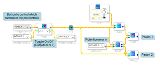
My question is how do I restore Param 1 to 0.3? I've made the following schematic... haven't tested it, but I imagine it's either right or nearly there:
Looking at this pic, what I basically want to do is get that Value Hold block (far right) for Param 1 to "remember" what Param 1 was last set at before the device was turned off.
Any suggestions, solutions, workarounds? I'm trying to avoid using a microcontroller, by the way.
Thank you!
Audio Signal Processors
Value Hold
SigmaDSP Audio Processors
adau1701
Hello Tony,
You did a great start on this but I think there is an easier way to do this but it is a bit of a creative use of some cells that might take a bit to understand. It does show exactly how the interface read and writes work.
I will paste in some pictures of sections but I will put in the entire project at the end.
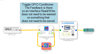
First the toggle function:
This is a creative use of a feedback cell. The note explains it.
So this will give us a zero and then a non-zero number each time the switch is pressed.
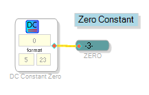
Then there is this little trick to use if you need to use the same constant in several places.
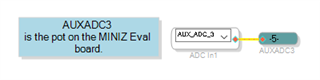
Then the AUXADC input needs to go to a few places so I used an Alias:
Now on to the meat of the program:
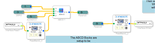
This uses the favorite block of KJBob and I. The ABCD logic cell.
So this compares the output of the toggle cell to zero. Then it either outputs the AUXADC Pot or the output of the Interface Read.
So the output of the ABCD cell will be sent to two places, one will be the parameter to be controlled and the second will be to the Interface Write cell.
How this works is that the interface registers are simply a memory location.
The interface write will write a new value into memory location.
Interface Read will read that location every sample period but one sample period delayed.
So the data is written to memory when the AUXADC pot
is active. Once the ABCD block changes to the Interface Read, the current value of
the memory location will be sent out. This value is the previous sample period so it
will lock in that old value.
Then when the power is going down the contents of the interface registers will be saved.
When the part boots back up it will pick up those values and the interface read
will send out those values. Of course the control that happens to be active when
it boots up will be set to the position of the pot at that time.
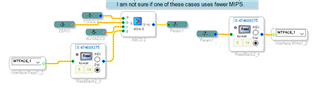
So for each parameter you set it up in a similar fashion. You could even have the external AUXADC drive a table to output several numbers and setup several ABCD blocks to only activate on a single number instead of comparing all of them to zero. It can test for "==" and use a DC cell to set the number it is comparing to. I just did this quickly and simply. But as I wrote this I already see an improvement to handle a large number of parameters. Of course you only have 8 different interface Read/Write locations.
Here is the program.
Hope this help.
Dave T
6574.ADAU1701 Recalling any parameter with AUXADC Index Selectable Filter.zip
That's simply awesome. Thank you Dave. I understood everything you said and the program too. And I learned some hacks. I really appreciate your time.
Please log in to reply.