ADAU-1452 Digital noise at Link compile Download
I am currently working on a small project with an ADAU-1452 where the circuit is identical to the evaluation board, except for the MP and I2S ports. The DSP is connected to a AK4468 DAC at OUT0, a I2S bluetooth module at IN0 and AK5572 at IN1. and the programmer is the original evaluation board programmer from AD.
I was working on the sigmastudio setup last night and had some issues getting the DSP to accept the programming when i used Link Compile Connect, and using Link Compile Download ended up killing a tweeter as a loud digital noise or long pop came out at the point of connection. Does anyone know what could be the issue?
I did also experience some weird issues with the 3 way autoEQ where the outputs started to shift, so High out was changed to Low out. Did i miss something in the hardware setup or what could be wrong?
Hello Colakurt,
When dealing with power amps and speakers it is certainly advisable to mute or shut off the power amps when programming the part. The state of the part can be unknown and the DSP is stopped during the process. This can cause DC to come out of the serial digital ports which can cause a loud pop. Many things could have been the issue so I cannot say for certain what happened.
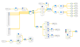
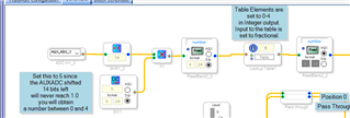
Thanks for including a snip of your program. You are not driving the MUX and the table properly. It is a little difficult for me to see exactly what you are doing because I would have to have the project itself but you have to be careful to not send data to a switch that is in excess of its valid selections. You have a three way switch so it should only be sent a 0-2 in integer format. 32.0. The table has 32 elements in it which is not needed.
Here is an example of one of my programs that drives a MUX with five positions.
Always place a readback at the output to check what is going to the switch. Once you are certain it is fine then the readback can be deleted if you are running out of space for your program.
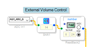
For your volume control, you should use 14. You have it set to 13 which will limit the volume control. It will not be able to go to the maximum level but perhaps this is desirable in your case.
You should consider putting a limiter on the outputs.
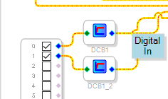
Another thing that can be important when dealing with speakers is to block any DC coming in. If you know it is coming from an ADC under your control and you have turned on the HPF that is built into many ADCs then you do not need to do anything in the DSP. But if it is from an unknown source I suggest you place a DC block on the input signals. The crossover filters for the LF section will do a great job of boosting the DC content and that can cause the pops and clicks when switching between signals.
Enough for now.
Dave T
As you can see from my circuit then i am using MP7 and MP13 to control mute and standby for my amps, they are both active high. I am not able to disconnect these options from my DSP, but i can disable the internal Pull down resistor and add an external pull up, this would essentially mute the amps as long as the DSP is not actively pulling the pins low. Would a solution like that work during programming?
The table contain 33 lines but they are only used to divide my elector potmeter into 3 sections, so 0-11=0, 12-22=1, 23-32=2 as the output of the table, so i think the MUX is okay, but know there must be a more elegant solution.
The volume control was adjusted with the internal VU meter and an active input source to ensure i would have some headroom, but you are right that i can set it to 14, but in my case i got 500W pr channel so I prefer to have some finer adjustment in the lower output range as this is a Hifi setup.
The ADC should both have an internal DC block plus the analog circuit have a HPF, but thank you for bringing it up, i might just add the block anyway.
For now my biggest concern is to have a safe way to program the amp without the need to unplug the speakers or amps every time i make the connection.
Hello Colakurt
Colakurt said:
As you can see from my circuit then i am using MP7 and MP13 to control mute and standby for my amps, they are both active high. I am not able to disconnect these options from my DSP, but i can disable the internal Pull down resistor and add an external pull up, this would essentially mute the amps as long as the DSP is not actively pulling the pins low. Would a solution like that work during programming?
Yes, it most likely would. When in reset the pin will sit high and it will remain high as the program is being loaded. Then the program will pull it low once it starts running. We have done this on the production tester so I am confident it will work. You will want to give it a test and look at it on a scope before you turn on the amps.
Colakurt said:
The table contain 33 lines but they are only used to divide my elector potmeter into 3 sections, so 0-11=0, 12-22=1, 23-32=2 as the output of the table, so i think the MUX is okay, but know there must be a more elegant solution.
I showed you the more elegant solution that is more likely to produce known output that is not going to exceed the index number. You at least need to test your setup using a readback to be certain about it. Many of our index controlled cells do not perform range checking so if it is given a number higher than the last index then the pointer will point to memory beyond the cell and in predictable things can happen. It depends on what object it is stepping on.
Colakurt said:
The volume control was adjusted with the internal VU meter and an active input source to ensure i would have some headroom, but you are right that i can set it to 14, but in my case i got 500W pr channel so I prefer to have some finer adjustment in the lower output range as this is a Hifi setup.
I just wanted to point it out. I suspected that you might be limiting the range on purpose. There are so many ways to do this.
Colakurt said:
The ADC should both have an internal DC block plus the analog circuit have a HPF, but thank you for bringing it up, i might just add the block anyway.
If you know the ADC has the HPF, I would check that, and the analog inputs have caps in series then you will not have anything to worry about. The DC block filters out around 2Hz and below or something like that so it does not really affect your audio to any great degree. So you could save MIPS and not include them. Whenever someone mentions noises and loud pops I want to be sure this is not the source.
Dave T
Please log in to reply.