Eurorack Peak / Rms to Gate
Hi,
I want to get audio into the adau1701, bandpass, gate and get a signal everytime the gate is active. At the moemnt I am using the limiter for that which is working great but on the GPIO I dont get 3.3 V each time the limiter is active. So my levelshifter doesn't shift to 5 V which I would need to trigger eurorack devices.
Is there any way of making the GPIO having just 2 states (either 0 / no limiting or 1 / limiting) so that I either have 0 or 3.3 V on my GPIO. If not are there any ready done modules or easy schematics on how to archieve that (I suppose the GPIO could make transistor open and close a 5 V signal?) Are there any details on that?
Also are the better dsp models faster than the 1701? So far it seems that 3 ms delay is ok but just to know - the sigma studio software is great and easy to understand unlike real programming.
I have another question - is there any frequency analyzer in the software or is there any way to do that (and display fft on a tft or oled or the note value)?
Thanks for helping
Jens
Audio Signal Processors
SigmaDSP Audio Processors
adau1701
Hello Jens,
You're on the right track with your limiter, since you have it working aurally. Either or both of two issues may be preventing your GPIO from working as desired. First, the Limiter block's output labeling:
Notice that the Limiters' middle pins are feeding the GPIOs -- the ones labeled, "Limiter Ratio," yet are really the Limiter Active Flags. So guess what the bottom pins do? That's right, the labels are flopped. Connect your GPIOs to the middle pins, and likely your project will work the way you expect.
If the GPIO outputs are still unresponsive, check your multi-purpose pin settings in the Register Control window. The MP pins in use (in my case, that's MP 10 & 11) need to be set for, "Output GPIO."
The Limiter measures incoming audio with an averaging RMS calculation, thus it's not instantaneous. You can increase its "RMS TC (dB/S)" number to make it respond faster. Try this first as it's an easy adjustment. If it's still not fast enough, try using a Peak Compressor, setting its curve to a limiting (flat above your threshold) response. These don't have any Limiter Active Flag output so you'll need to substitute your own level-sensing circuit adjusted to trigger the GPIO at about the same input level which causes limiting. You can get help with any of this if needed. Once I did a crazy-complex instant limiter, but I don't recommend it anymore since the ADI blocks are far more compact.
The SigmaStudio function blocks are generally designed to work the same on any of the DSP chips, so the Limiter as such won't work any faster on a more advanced chip. The larger chips do have an advantage, though -- with more instructions available, you can operate at a higher sample rate while still having enough program space to do all you need. Also, the ADAU1452 and above have FFT capability. So far, though, there's no built-in SigmaStudio blocks to quickly implement a spectrum analyzer.
Best regards,
Bob
Hi Bob,
thanls for your answer.
I am getting a signal on the gpio and can drive a led. My goal is to create gate signals for eurorack which need 5 V. Using a levelshifter was unsuccessful unfortunately (3,3 to 5). I dont get full 5v as far as my slow multimeter is showing and csnt cause the modules to play :(
The ADAU1701 datasheet only promises 2.0 volts worst case:
So you'll need to adapt your level shifter accordingly. Which reminds me of an old joke:
Q: How many programmers does it take to change a light bulb?
A: That's a hardware problem!
Best regards,
Bob
Thanks a lot for helping :)
I am using a levelshifter now and get 5 V out which is great. Unfortunately if I put a switch on a gpio in Sigma Studio and switch it on - so full output (which I measure with 3,3 V but this might be due to the lvel shifter operating at 3,3, not sure though).
I need to have something that gives either 0 V or full output once a given threshold is reached and goes back to 0 after the signal is below the threshold. I dont want the audio signal I just want to get a full output out of it so I can shift this to 5 V and trigger my eurorack with it.
So if I use the level detection block which unfortunately has minimum 2 secs I can get either 0 or 5 V on the other side of my level shifter but well 2 seconds is way too slow. I need peak, ideally adjustable how many samples, rms would be ok as well as long as the out put isn'T the rms value but just a on or off.
Is there any way to do this?
Sorry for maybe asking obvious questions. If I connect a on off switch to the GPIO I read 3,3 V and on the other side of the level shifter 5 V. So I tried almost everything (Also the tolerance analyzer which was connected to the output 2 of the limiter which I understood should make in signal 2 (in my case the switch that is set to on) pass to the output (which in my case is connected to the gpio pin and got me 3,3 and 5 volt without any module in between) but except using a switch turned on directly on the gpio I can not get any signal that comes up to 3,3 V out of the pin.
So I am wondering i the pins are maybe not fast enough for those fast movements? I probably could reduce v in on the levelshifter to get more close to what the dsp is giving out on the gpio to reach the threshold (about max 10% difference to the incoming signal to get the lvels shifted up to 5 V but I just dont get it.
If the gpios just arent fast enough It would be great to know. Maybe an alternative was to set a squarewave with a very very low frequency oscillator on each mono out and try to switch this on and off using the signal of the limiter. I have a teensy 4.1 as well but the Sigma Studio Software is really nice to use and the Teensyduino Library is not that complete compared to the Sigma Studio.
Cheers,
Jens
Hello Jens,
The GPIOs can operate at the full sample rate -- I have a scope waveform to prove it but unfortunately, I no longer see in the editing menu below any way to insert such a picture, provide a link, or do anything except text! I also built a circuit which uses an Envelope Follower and a ABCD Comparator to provide a really fast GPIO output responding to audio levels above or below an adjustable threshold -- this is what I think you're looking for. The way the forum is presently working, I cannot show you the schematic nor attach the project. Try sending me a friend request, I'll approve it and send you a PM -- the last time I looked, the PM system still works properly.
*** Edit: As of right now (7/30/2020 10:45 am EST), my full edit window has disappeared for PMs as well. What on earth is going on?
Is anyone else having problems with the forum software besides me? Could someone from ADI investigate this issue? Really, the row under this window has only buttons to pick font size and bulleted / numbered lists. That's it. No way to insert a picture, a file, a link, or anything else needed to explain stuff. A picture is worth a thousand words, so please bring these back!
Best regards,
Bob
Thanks Bob!
I can see the full editor view. Files, lists, tables, tools, images.... all fine.
Even if the editor has been hidden somehow, you should still be able to paste images to the editor, and drag files from File Explorer onto the editor to attach them.
Let me know if this issue keeps happening.
Joshua
Hi Joshua,
Thank you for checking out the issue. It's still happening on this reply, even on another PC with a different browser. I posted the issue on the Help with EZ board, where I could show an image -- so if desired, you can see what I/m seeing. Hopefully the staff over there can address the issue. I'll help jenskuehnemann via PM for the moment. Again, thank you for your concern.
Bob
When I hit reply, I see something like this:
In fact, it let me just paste the screen shot in. If you don't see that, and you don't get a response from the board admin, definitely let us know. Great to have you back!
Ken
THanks a lot for your help it is working very well. I was wondering if the trigger signal could be split and be used to trigger a block measuring the level of the signal that caused the trigger (so an envelope follower basically)?
Best regards,
Jens
Hello Jens,
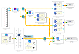
Above is shown the discrete signal detector we came up with via PM so others can follow. I can now show pictures here, but still not attachments.
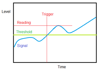
You could certainly have the signal detector trigger a level reading -- yet triggering this reading at the moment of signal detection will invariably provide a reading at or very close to the signal detect's threshold, In other words, nearly the same reading every time. Perhaps what you're looking for is to capture the first peak level immediately after the threshold is crossed & the signal detect activated. Its response would look like this:
This is possible as well. Please let me know how you wish this level measurement to work.
Best regards,
Bob
Hi Bob,
Thank you so much for your help. If I understand correctly I think this is what I was looking for. So if possible for every signal that goes above the threshold it would be great to read its highest peak or something like this to for example like when having a drumroll being able to catch the dynamics
If there now also was a way to roughly detect the frequency (like having a certain amount of time and counting every time the signals passes 0 and so get a rough idea of the signals pitch) this would be the basis for a really interesting thing.
Again thank you so much for ypur help. Also could you recommend a good book to get into the ideas of dsp programming? I am a dentist and trying to unddrstamd as much as I can but I would love to have deeper understanding.
Thanks a lot and hi from Berlin :)
Hello Jens,
I've tried a few ideas for the peak capture yet none have worked well so far. I'll try again when time permits, of course others here are free to help as well. And it won't be long before you'll be designing on your own!
Many SigmaDSP designers aren't DSP experts -- for example, a musician built an ultrasonic blind assist device using a ADAU1701. Your first step is to learn more about SigmaStudio itself and how the blocks work and interconnect. You'll find these resources helpful:
The SigmaStudio wiki -- https://wiki.analog.com/resources/tools-software/sigmastudio Here you'll find the Toolbox describing how all the blocks work, what inputs they expect and outputs they provide. And lots of other helpful stuff.
Documents / FAQs -- https://ez.analog.com/dsp/sigmadsp/w/documents Perhaps the most useful of these for beginners describes the integer and decimal number formats used in SigmaDSP.
You'll learn the most by building and troubleshooting projects, referring to the docs as needed. Once you're comfortable designing with SigmaStudio, the next step could be this book which AD and its author have graciously made available to download:
https://www.analog.com/en/education/education-library/scientist_engineers_guide.html
The musician I mentioned above studied this book as have I. It's quite accessible yet you can go as deep as you want. It will help with your DSP projects in ways easier to experience than to describe.
Happy designing!
Bob
Thanks a lot for your help :)
So far the project is going extremely well and exceednig my expectations already. I still have some questions but I think it would be a good idea to open a new thread for this.
Also your ideas regarding frequency detection / analysis to CV do work very well (havent figured out how to implement the hysteris comparator though) and the results actually are giving me lots lots of more ideas. The project already went way above what I imagined first place.
I just got an idea. The circuit you showed to me is working really well. I could take a clock signal from a modular system and feed it to an audio in. Using the circuit above and setting it up properly I should end up with a pulse every time the clock ticks. So it should be possible to use those for switching things within the dsp time relevant. Without knowing the different modules I am sure there is a way to easily double the tempo, half the tempo etc.
Hope this isn't nonsense what I am thinking of but if this would work this would be one of the last bits missing to make the dsp a flexible system for eurorack ideas to control things rather than "just" process audio.
Hi, I have got another question regarding the gpio outut. Is there any way to incorporate something like sample and hold so I can set a minimum length a gpio has to be "on" before allowed to switch off and trigger again?
I was looking through the modules but didn't find something that is like "once active stay active for the amount of x millisecons or samples". The hold module requires another signal to keep it holding.
Oh and another question. How would you control Threshold over I2C as it is using negative Values?
Thanks for helping :)
Hello Jens,
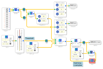
To extend the minimum length for your GPIO to be high, you could add a few blocks just before the GPIO as shown below. The One-Shot Rise triggers high with any input pulse and would stay high indefinitely if it weren't for the Timer with Reset (under Counters / Stop Watches in the Toolbox). The Timer's count (in samples) is set by the integer DC Source. Once the Timer times out, it resets the One-Shot. Today once again there's no provision to insert a picture in my post here. I'll try making another post.
Hi Bob,
Thanks for your answer.
So when I am running on 48kHz and I want a 30 ms triggerlength I suppose I then enter 1440 samples (30 x 48). Is there a way to limit the output to those length as well so that the GPIO on can only be 30 ms even if the peak is held for much longer than 30 ms?
I am also wondering whether I am doing something wrong. When my threshold is way above th signal from the envelope peak I also end up having a constantly high GPIO.
Not sure if I understood correctly. The envelop peak does start sending values of the incoming level and once the incoming level decreases it keeps sending the last highest value for the amount of ms set within the hold parameter, once this time has passed the value sent decreases with the speed set in decay rate. If during this period a higher level comes in again the block will send the value higher than the one it just sent until the value drops again once it drops the block sends the highest value for the time set in hold and starts sending lower values after that, the values after that depend on the decay rate.
The comparator compares the values coming from the envelope peak block (a) to the values coming from threshold (b and c) which is basically a 1 reduced by the setting of the fader threshold (so anything less than 1). If the value of envelope peak (a) is higher than b or c (b=c) then it is going to let a pass if not then it lets d (value 0) pass. I probably got something wrong as the triggers are full level so it can't be the value of a that is let through (except a is not the absolute value of the peak but just a on or off - in that case when does it switch from on to off?). I am wondering how I get a positive output on the GPIO if the Threshold is way above the Level of a. Is there a way to just get a positive output if the threshold is below a? At the moment there seems to be a range when the triggers are generated and the output is high if above or below that range.
I also controlled hold and decay with pots but instead of extended flexibility it is getting quite unclear how the parameters affect each other / the generated trigger. So I thought I choose something between 50 and 80 ms for hold to just catch the transients I suppose then a very fast decayrate is advised to limit triggertime (except the material is commpressed with way too fast attack time.
I hope that makes sense.
Cheers,
Jens
Oh I frogot to mention. There is a way to set it up that triggers are gnenerated even after switching off the input signal
Hello,
Sorry I had forgotten to post the project once my attachment ability returned. I believe this was the one (it's been some time). It has a timer to allow the trigger to remain after the signal stops, you can adjust the time with the DC source.
Best regards,
Bob
Discrete-SD (2).zip
Please log in to reply.