Pitch detection adau 1701
Hi,
Is there any way to implement a rudimentary pitch detection on the adau 1701 (so for example analyze how often the signal crosses 0 in 0.5 sec or whatever would be an appropiate value for measuring (I suppose max 1/40 of a sec as further down it isnt needed) and calculate periods over time and give out a digital value or a corresponding current on a gpio?
Cheers,
Jens
Hello Jens,
A Value-Cross block produces a pulse one sample wide for each zero-crossing, thus if forms the basis for (in analog terms) a "charge pump" frequency-to-voltage converter. An example is shown in this post
If the resulting measurement is erratic, try setting up a ABCD comparator with hysteresis before the Value-Cross block.
Best regards,
Bob
Thank you so much for your help :)
the frequency analysis is working quite well so far. I didnt manage to get the shown example with the feedback on the comparator working yet but this isn't a huge problem. The setup already as it is is stunning.
Now I was wondering whether it is possible to do the following things:
As soon as an event causes an output of current relative to its frequency is there a way to keep the initially "measured" frequency? So if I have an incoming signal (probaby the worst signal for this but lets think of a drumloop) I can now generate Triggersignals as well as a current relative to the frequency of the incoing signal. This is working way better than I expected to be honest.
When using a drumloop fpr example a lot of triggers can be generated depending on the setting of the rest of the circuit. So it happens that the frequency to cv current goes up and down somparable to using a pitchbend wheel on the synth. Is there a way of keeping the current stable for x milliseconds or until the next trigger is generated? I suppose a sample an hold module might be used for this but I dont know.
Also for the current that is generated in releation to the frequency is it possible to force it to be just certain values? So instead of going up and down wildly could I restrict it to discrete values? So instead of allowing a sweep through the spectrum it will jump from frequency to frequency depending on which of the allowed frequencies is closer to the on that is measured at this moment? I hope this makes sense. So that I could setup one (or even better certain selectable) scales so my CV would automatically play in the right scale?
If the timing as well as the scale were possible to do in the dsp it would be amazing. Timing could be done by the mcu doing the i2c control by switching on and off outputs or changing values peiodically but if it could be done within the dsp it would be great.
Thanks everybody for helping so far. The project already is way better than expected :)
Hello,
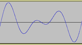
Good to hear that the F-V converter is working for you. Its ability to work with real-world sounds is limited by ambiguous zero crossings inherent in many such sounds. Sounds with harmonics and especially chords can intermittently cross zero more than twice per fundamental cycle. For example, the waveform below is from two tones a fifth apart, as often found in music. With more than one frequency involved, it cannot be measured by simple methods:
This effect as well as noise may contribute to the variations you're experiencing. You can "freeze' the F-V converter's output with a Value Hold block, but of course the challenge is coming up with a trigger signal to start the hold while the F-V output is correct. A simple example would be to trigger upon your audio's amplitude peaks. It's also quite possible to arrange for a "holdoff" time as you described. However, such a timer prolongs both correct and incorrect measurements.
It would not be difficult to quantize the F-V output to discrete, evenly-spaced steps. If instead you wish them to be exponentially spaced -- like notes on a piano -- this is more complex. You could, for example, take the base-2 log of the F-V output. Then scale, offset, and quantize this into an integer from 1 to 89, and have it drive a lookup table filled with the decimal values corresponding to each note. I haven't tried this, and suggest not attempting it unless / until you have the triggered F-V working to your satisfaction -- as it's quite a bit of work.
Best regards,
Bob
Hi Bob,
Thanks a lot for your answer. As usual this helps a lot. I have to try tomorrow but am confident that this is going to gibe the project even more.
I am aware that wrong readings will happen, especially when dealing with drums that are having very high transients but a way deeper body. Even if a 100% true f to v conversion would be awesome this is something I can work with very well. If the block you mentioned allows to "freeze" the frequency it wont go all over the place and gives room to work with it.
There are quantizer modules in case such a function is too difficult to implement.
Could this block also be used for triggersignals to set a minimum length?
It is getting more and more interesting. I saw logic modules from which I don't know how they work but I suppose triggers also could be multiplied or divided.
When measureing the output I still get some negative values. Is there any way to prevent this within the dsp or do I have to implement rectifiers after the da conversion?
I was also wonderin whether there is a way to feed a clock signal into the input and use this for time depending actions.
I am having so much more ideas where to go with this and I have to say that I am really impressed already by the results when using it in a eurorack environment.
Anyway, thanks again for your help I am going to try what I csn do with it.
Have a good Sunday :)
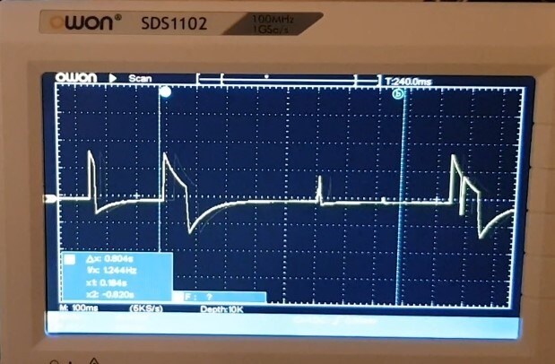
OHh and I am getting some AC.
Is there any way around this?
Hello Jens,
Are you seeing this waveform at the audio output of a ADAU1701MINIZ or any similar board? There's a AC coupling cap between the DAC output and the board's audio output, which will center the resulting waveform at zero. This means that whenever there's a positive excursion, it will always be followed by a negative one -- the scope picture will appear like AC. The area below zero of the negative excursion will equal the area above zero of the positive one -- as a result of charge balancing in this cap.
To see a DC level result, you need to get to the DAC side of this cap and measure there. Because the ADAU1701 is a single-supply device, the DAC output sits at Vcc/2 (about 1.6 V) when your project outputs zero. It goes down toward zero with positive numbers, and up toward Vcc for negative numbers (that is, the DAC inverts the signal). Where I work, one of our products feeds level information from DACs to ADCs in the system's uC so it "knows" the audio level of all channels. Because the DACs' offsets (the lowest analog outputs with a full-scale positive number) vary from chip to chip and likely with other variables, we implemented auto-calibration. At each power-ON, the DSPs set their DACs to full scale, the uC measures each "zero" level and saves these values to subtract from subsequent readings.
Best regards,
Bob
Hi Bob,
Thanks for your answer.
I am using a wondom (ex sure) board.
Would it be possible to pull the signal just from before the cap or would it have to be cut off / removed.
I dont mind pure accuracy regarding the frequency. If I understand right the cap just shifts the zero upwards.
I am gonna have a look at the datasheet and measure before the caps tomorrow or so.
Thanks a lot for helping again.
Best Regards
Jens
Also having a cheap eval board 1401 which let me pull the signal before. Didnt measure but wirh the hold block + timer it worked very well already
I am having problems with the cheap eval boards which work great with the programmer but not with a mcu.
What is it that the programmner does different. I am gonna record the oszi the next days.
It is just connected to i2c wp and thats it. No reset on chesp china boards and working perfectly. It would be nice thought to have the teensy control it. In case the project would get succeddful we would do a design in kicad and make custom modules but there are so msny vsrisbles so fR.
I2c on the 1t01 being the worst.
Again let me say thanks a lot. You really helped pushing tve project to a plsce I never thought it could be.
Just played with it the last 4 hours instead of working on it as it is so nice
Please log in to reply.