Need help to put DSP in SPI mode, using microcontroller.
Hi
Im trying to put ADA1401 in SPI mode, but without success, so i will need some help.
First, i do not have an oficial board, i have cheaper chinese one, and this board missing pin header for ADDR1/CDATA/WB, so, i wired him soldering ( there is already, a pull up resistor on that pin +3.3v ), so i dont know wich is, my SPI routines or my board that have a problem.I have tryed to read one single register ( Core Register ) from DSP ( both SPI address ).
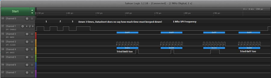
Put CLATCH/WP dow 3 times, then send ( 0x01, 0x08, 0x1c, 0xFF, 0xFF ), DSP not responds.
Put CLATCH/WP dow 3 times, then send ( 0x03, 0x08, 0x1c, 0xFF, 0xFF ), DSP not responds.
Also, i have swaped MISO and MOSI lines at DSP side, same result.
Connections DSP - Microcontroller
CLATCH/WP - SPI CS
SCL/CCLK - SPI Clock
SDA/COUT - SPI MISO
ADDR1/CDATA/WB - SPI MOSI
PS: This board has SELF BOOT from EEprom Enabled, so i do that procedure after boot complete.
All captured imgages was made on DSP board side, to make shure, wire has not broken/corrupted.
Attached an image from Logic Analizer, usign SPI with 1Mhz Speed and Microcontroller.( i have now changed this, to fit USBi, i will upload another image )
Attached image from logic analizer with USBi, this shows some points:
a) Put DSP in SPI mode cant be captured, maybe too fast?
b) USBi change clock speed between request ( 333khz) and read data ( 666khz )
c) USBi wait 300 microseconds ater write address, to read data, so DSP takes much time to process read?
d) USBi uses 0xff to clock received data
Thanks
Best regards.
Edit Notes
Adding more info.
[edited by: Rocha at 4:47 PM (GMT -4) on 22 Oct 2020]
Audio Signal Processors
adau1401
spi
usbi
SigmaDSP Audio Processors
CLATCH
adau1701
ADDR1
Show More

Please log in to reply.