How to handle non-standard TDM protocol?
Hello,
I am looking for an audio DSP that can handle a non fully standard TDM protocol.
It is like a 16 bits 8 bidirectional channel TDM8 but instead of using 32 bits per audio channel on the DATA line, only the actual 16 bits audio data are present, there is no padding bits.
Furthermore, an additional padding channel is present at the end of the frame, resulting to 144 data bits per frame (with only 128 bits for the payload).
The sampling rate is set to 16 kHz, so the bit clock frequency is set to 2.304Mhz.
Is there a product in the SigmaDSP product line that can be compatible with this protocol?
Thank you.
EDIT:
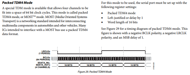
In the ADAU1452/ADAU1451/ADAU1450 datasheet there is a mention of a mode called "Packed TDM4", with only 16 bit clock cycles per channel.
In my case, it could almost be called "packed TDM8", plus 16 extra bits at the end of a frame (and LRCLK as a pulse).
Edit Notes
edited
[edited by: Lanny at 1:13 PM (GMT -4) on 30 Oct 2020]
Hello Lanny,
The ADAU1452 can take this signal in as a slave no problem. There are some tricks to doing it that I will expand on below.
As a master it cannot produce the 9 channels of TDM. It can only do 2,4,8,16.
The reason why it is fine as a slave has to do with how the serial ports work. At the start of the frame they start shifting in the data into a large bank of memory with no channel boundaries. Then at the end of the frame it moves this over into a buffer for each channel. How this large block of memory is divvied up between the channels depends on settings. There are a few more details that are not important to this discussion. If the input signal has more bit clocks than needed for the setting the data will simply be stuffed into memory that is not going to be transferred anywhere at the end of the frame or if it is more than 16 channels of 32 bit wide slots then the data will fall into the proverbial bit-bucket and be ignored.
So this means that if we were to set the serial port to send or receive 8 channels but it gets nine channels of clocks, the ninth channel will simply have no data or be ignored. So this applies to both the serial input and output ports.
If the serial port is setup as a master then we only can put out clocks that are detailed in the registers and the registers cannot do nine channels.
Regarding the packed format of 16 bit data. This seems like an issue but it is not, we can handle this in software with a few special hardware settings.
We do have the packed 2 and 4 channel TDM 16 bit formats directly available as a register setting. The trick to getting more channels is what requires some software.
We have two blocks in the library of SigmaStudio that pack and unpack 16 bit data into one 32 bit word. Then the serial ports can be setup for 8 channels of 32 bit data. This will give you 16 channels of 16 bit data into one 8-channel 32 bit stream. Then you also have to set the interface between the serial ports and the DSP core to be 32 bits so it does not truncate and saturate the 32 bit data into the usual 24 bit data. Once the 32 bit data is in the core then the DSP will split it up into two channels of 16 bits.
This all works well and has been done many times.
So we can certainly accommodate this unusual format as a clock slave.
Dave T
Dave, thank you very much for this quick reply.
But I don't understand why I need to setup 8 channels of 32 bit data (256 bits).
As I only need 128 bits, using 4 channels of 32 bit data should do the trick, right?
Hello Lanny,
Actually, you probably could setup for 4 channels of 32 bits to get the 8 channels of 16 bit data and I am certain that the last ninth channel of data will be ignored.
Keep in mind, I am not saying you have to put out 8 channels of 32 bits, I am saying you setup the DSP to receive 8 channels of 32 bits and if you only send it 128 bits then that is all it is going to get. We can split up these 128 bits into 8 channels of 16 bit data.
I put a lot of info on the post.
Basically, If you can output 144 bits of 16 bit data we can read it. We just will not be able to produce this exact clock output as a master clock source. The clocks will have to originate from outside of the DSP.
Dave T
ADAU1452 evaluation board ordered.
I have some experience with ADAU1701 but the 1452 is an other beast with much more blocks and IOs.
Hello Dave,
I received my EVAL-ADAU1452RevBZ board and I am currently trying to get it working with my device.
While everything works fine when the DSP is running as a slave (LRCLK and BLCK as inputs) at 48 kHz, it does not work with a frame frequency set to 16 kHz.
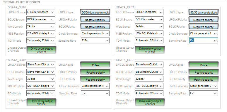
My simple schematic to test the DSP is as follows:
A constant value (0xAAAA5555) is sent to the four outputs.
LRCLK_out2 and BCLK_out2 are provided by an external master (either my device or an ADAU1701).
The serial port 2 is set to slave with 4 channels of 32 bits.
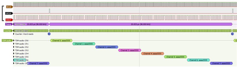
Here are the results when the signals come from an ADAU1701 @48kHz:
Note that the channels 1 to 4 are duplicated to 5 to 8, but it is not a problem.
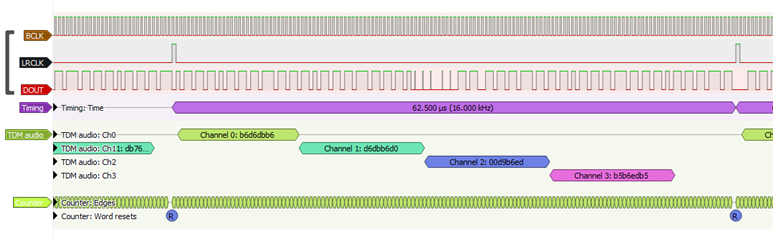
And here the results when the clock signals come from my device @16kHz:
I tried to set the Start Pulse to 'Base_Fs / 3' or 'Serial output 2 rate', or SDATA_OUT2 samplig rate to '32kHz / 2' but without success.
Thank you for your help.

Please log in to reply.