Improper operation of the Feedback module
Hello!
I made a circuit with a feedback using a feedback module, when this circuit is working at the output, the signal should be zero, because a signal in antiphase is applied to the input of the adder.
But there is a signal at the output, when you try to compose it, the signal rattles at the output.
Project and photos of the work on the link.
How can you refuse the feedback module? or fix it?
https://cloud.mail.ru/public/deBr%2FKHyR6EnkN
Edit Notes
Edit
[edited by: TheDenwww at 12:23 PM (GMT -5) on 10 Jan 2021]
Hello,
The Feedback module re-introduces its input (right side) to its output (left side) at the next sample interval. Thus its path adds a one-sample delay. The two-input Signal Merger adds its inputs with a loss of 6 dB (it multiplies the sum by 0.5). Combine these two functions in the circuit you've shown, and it turns out that they're both working as expected. We can explain this in two steps.
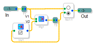
First, assume that we could add feedback as in an analog circuit, simply by wiring back -- as shown below:
The Signal Merger performs the function Vout = 0.5 (V1 + V2). With the feedback (V2 = -Vout), the circuit's transfer function becomes
Vout = 0.5 (Vin - Vout) which solves to: Vout = Vin / 3. Thus even without the one-sample delay, this circuit has a nonzero output.
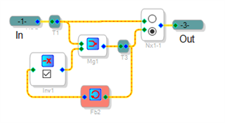
The DSP executes your entire SigmaStudio project each sample interval. The inputs for every module have been determined by the previous sample's run, the modules calculate their outputs, and these are retained for the next sample's run. Since every module can perform only one operation during a particular sample interval, any feedback must wait for the next sample run before it applies. Thus the Feedback module always adds a one-sample delay -- and if you try to run the project as shown above, you'll get the Illegal Feedback error. There's simply no way around this. With the Feedback module included (as shown below), its delay makes the circuit more complex:
Now the circuit's operation must be described by the difference equation:
Vout(n) = 0.5 Vin(n) - 0.5 Vout(n-1)
This amounts to a first-order digital filter with coefficients a0 = 0.5, and b1 = -0.5.
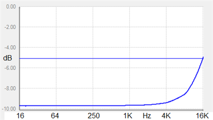
Its transfer function is H(z) = 0.5z / (z + 0.5). It has a zero at 0, and a pole at -0.5. Since the pole is within the unit circle, this filter is stable and has a measurable frequency response. Calculating the response is beyond my ability, and unfortunately the Stimulus-Probe tool doesn't work when Feedback modules are included. I've built a project using a swept VCO to measure the response of whatever's inserted inside -- and with this circuit inserted, the response appears as shown below. It has a gain of about -10 dB below 4 KHz, rising at higher frequency:
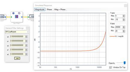
It's also possible to model this filter by entering its coefficients into the IIR Coefficient window of the General Second-Order Filter. Here the a and b coefficients must be flopped, then the a0 coefficient negated, because SigmaStudio uses a different convention for the coefficient names compared to the textbook I'm studying:.
One of the circuits you've shown includes a gain of 10 dB (about 3) in the feedback path. This changes the transfer function to H(z) = 0.5z / (z + 1.5). Its pole at -1.5 is outside the unit circle, thus this circuit is unstable -- explaining the hash showing on your scope.
If nothing else, this analysis demonstrates that the Feedback module is working as designed. Thus, there's no way to refuse or fix it. Perhaps your application can be handled in another way, and the folks here would be happy to help.
Best regards.
Bob
Please log in to reply.