SigmaStudio v4.6 ADAU1467 configuring the SDATA inputs/outputs
Hi,
I am currently working with SigmaStudio v4.6 and I am planning a new design that will use the ADAU1467 for the first time.
I am trying to get all the Serial ports configured to all run off clock domain 0 (input for inputs and output for outputs).
In SigmaSudio, hardware configuration, serial port tab:
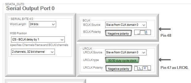
I am setting serial output port 2 to be a slave from clock domain 0 _BUT_ the pin numbers that this "diagram" shows are always those for BCLK_OUT_2 and LRCLK_OUT_2 when I am expecting them to change to be pins 47 and 48.
Is this a bug in SigmaStudio or is there something else I'm missing here ?
thanks for your time
PhilipJ
Audio Signal Processors
adau1467
SigmaDSP Audio Processors
Hello ,
Sorry for delayed response.
Can you please confirm, which diagram are you talking about ?
If you are asking about below diagram, please note that it will not change as pin 47 & pin 48 and it is not a bug.
Regards,
Lalitha.S
Please log in to reply.