Ext Slew Volume Control (HW Slew)
Dear Team.
I am analyzing the Ext Slew Volume Control block and have the following queries
1. How are the values measured? What is the tool/procedure used to arrive at these values that have been consolidated in the table above?
2. Looking at the GUI, it is evident that the ramp up is RC while ramp down is exponential . So does that mean that the values above in the table will only be true for ramp up ? If yes how do i measure values for ramp down?? By what factor will ramp up and ramp down values differ from each other ?
3. Are the values provided in the table measured only for one time constant that is 63 % of the target value or are these values for full slew 100% of target value ?
Regards
Hermione
Ken
KJ BOB
SigmaDSP
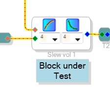
Dear Team!
Please provide your feedback for the query above since this imperative to our understanding of the Ext Slew Vol Control Block .
Your quick response in this regard will be highly appreciated!
Regards
Hermione
Hello Hermione,
Question 2:
The RC circuit's response to a step increase from 0 to Vm is: V = Vm * (1-e^(-t / T) where T = time constant = R*C.
The RC circuit's response to a step decrease from Vm to 0 is: V = Vm * e^(-t / T). Note that both rise and fall involve the e^x function, thus both are exponential in nature. Thus the RC block's time constants are the same for both rise and fall.
The HW Slew Volume Control also features an explicit Exponential setting. Its response to a step decrease from Vm to 0 is also V = Vm * e^(-t / T). Thus its falling time constant to zero is the same as that of the RC rise and fall for this case. On the other hand, a fall to a nonzero goal has its own unique timing. And its rise is nothing like that of the RC circuit -- unlike the RC rise and fall, there's no way to duplicate the exponential rise with only a resistor and capacitor. You'll find a description of the exponential slew here.
Question 3: The values given in the table are for one time constant -- a rise from 0 to 63% of Vm, and a fall from Vm to 37% of Vm. By definition, an exponential change never reaches its final value (it takes forever to get to exactly 100%). You could estimate practically the "100%" time if you multiply the RC time constant by 5 -- this gets you to about 99.3%
Question 1:
Between the tables I made and the Python script which @matthijs has produced*, we have thoroughly documented the slew characteristics. I would really like to put this one to bed. (*not all of us do Python, unfortunately. When I went to school there were still a few vacuum tubes in the lab, and I learned only FORTRAN, BASIC, Motorola 8-bit assembler, and embedded C.).
That being said, attached below is a SigmaStudio project like the one I had used to measure the slewing times. It measures the 10 -- 90 % times for any sort of rise and fall (in samples). For RC and falling exponential where time constant is related to the rise and fall times divided by 2.197, it calculates the RC time constant as well. It was designed to characterize the External Slew block only. Its operation can be explained with two diagrams:
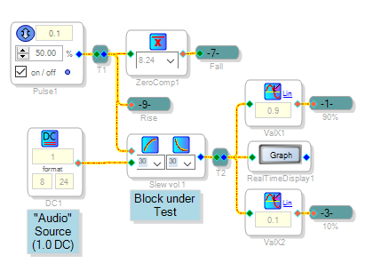
The first part of the project exercises the External Slew Volume block under test..
Pulse1 provides the timing for the whole circuit. It must be slow enough to allow the Slew Block to "completely" rise and fall -- about 10 time constants is enough. Thus with the present setting of 0.1 Hz -- 5 seconds up and five down -- the maximum time constant this circuit can accurately measure is about 0.5 seconds. Reduce the frequency further for extremely slow slew settings.
The pulse is directly applied to the Slew block's red control pin. A 1.0 DC source provides the "audio" which is modulated by the slew block to produce a measurable slewing output. Why DC? The Slew block's audio input, like that of most SigmaStudio blocks, is perfectly happy with DC. And the resulting slew rise and fall times are easily measurable. If a sine wave (for example) input were used and we attempted to measure the resulting slew with an envelope follower, the settling time of the follower could easily exceed the slew time we wish to measure -- or else the ripple from a fast-responding envelope follower would introduce errors in the slew time measurement. This is why most multimeters settle upon a DC reading faster than an AC one. It's a compromise we need not live with here, since the Slew Block works fine with a DC input at its blue pin. Unfortunately this is why the project as shown is unlikely to be of use for you, since from our PM exchanges your interest appears to be measuring the rise and fall of sine wave envelopes over a wide range of times / frequencies.
This portion of the project outputs four signals which the rest of the project uses to count the rise and fall times:
A logic 1 for the Rise (high Pulse1output)
A logic 1 for the Fall (low Pulse1 output)
A pulse when the Slew crosses 0.9 (90% of 1.0)
A pulse when the Slew crosses 0.1 (10% of 1.0)
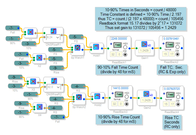
Here is the time-measuring logic:
The four multipliers gate the signals from the first section appropriately -- this is needed because the Value Cross Detectors provide a pulse when their threshold is crossed in both up and down directions. The One-Shots start the timers to count samples during a rise or fall. Timing stops when the threshold is crossed. The Hold blocks keep these times even after the timers get reset for the next measurement. A known formula is applied to convert rise and fall times to time constant -- for RC and in yhat one case of falling toward zero, the exponential.
Best regards,
Bob
Slew-rate-RC-1452 .zip
Please log in to reply.