EVAL-ADAU1701MINIZ – High Crystal Drive Level
EVAL-ADAU1701MINIZ – High Crystal Drive Level
Hello all,
I’ve read some posts regarding the ADAU1701 Crystal start-up issues, so I have made some measurements based on the ADAU1701 Evaluation module (EVAL-ADAU1701MINIZ)
When I measured the input amplitude in the crystal node, I saw something very strange.
I used an active probe with 0.5pF input capacitance in order not to influence my measurement.
I noticed that the amplitude at the crystal input is very high and distorted, while the input and output waveform should be a nice clean sinewave:
The crystal output looks much less distorted, but it makes sense due to the crystal filtering characteristics.
The evaluation board uses the ABRACON 12.288MHz crystal which has a drive level of 100 Wµ max., 10 µW typical.
If we take the maximum value of 100 Wµ, the maximum allowed amplitude should be around 2Vp-p
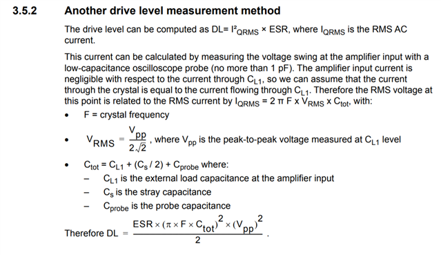
I used the formula written in the ST application note AN2867:
ESR = 70ohm
CL1 =CL2 = 22pF
CS = ~ 2pF
Cprobe = 0.5pF
Ctotal = 22pF + (2pF/2) +0.5pF = ~24pF
As shown above, the crystal input amplitude that I have measured is ~ 3.5Vp-p
So, DL = [ 70 x (pi x 12.288MHz x ~24pF)^2 X (3.5)^2 ] / 2 = 367uW !!!
As you can see, the drive level is out of spec…about 3.5 times the maximum value, this is the reason why the crystal waveform is so distorted.
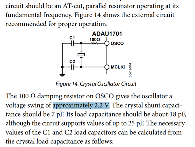
Looking at the ADAU1701 it is mentioned that:
The PDF claims that using 100ohm resistor gives a voltage swing of 2.2V…well, as show, this is far from being the truth.
Can somebody explain why the actual evaluation board measurement shows a 3.5p-p, while the PDF states the more appropriate amplitude swing of 2.2V.
Thanks a lot
Nir

Can anyone assist with the above?
Thanks
Nir
This is urgent!
Nobody from analog devices support engineers can address this problem?
Why does a customer is completely ignored from a critical issue?
Very disappointing and very unprofessional
Nir
Please log in to reply.