ADAU1701 basic clock issue/question
I've designed by own board based around the ADAU1701. I've followed the datasheet as best as I could down to a T and used a tight layout with best practices. I seem to be stuck at the most basic issue - generating a clock signal. From my research I should be seeing around 2V swing at MCLKi. However I am only seeing a steady DC voltage of 1V at MCLKi. On OSCO, I see a 12.288mhz sine wave 1V Peak to Peak (between 1V and 2V). I tried swapping out the ADAU1701 but it's the same thing. Crystal is an HC49-S at 12.288 MHz with 18pf load capacitors, and a 100 ohm damping resistor. I've been over the layout and design over and over and can't find anything wrong.
My question is, for those with eval boards or your own designs, what are you seeing in terms of voltage swings at these two pins? Is MCLKi perhaps current driven in this configuration? I have nothing to compare to.
Thanks in advance for any advice.
Edit Notes
Clarify question
[edited by: djamps at 5:59 PM (GMT -4) on 11 Jun 2021]
Audio Signal Processors
SigmaDSP Audio Processors
adau1701
Hello djamps,
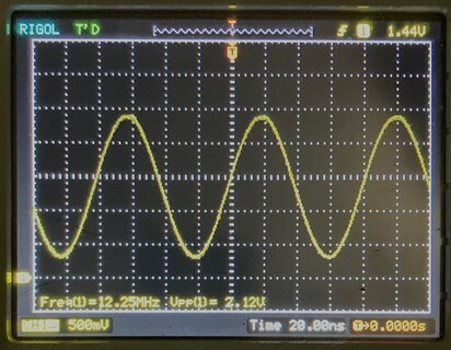
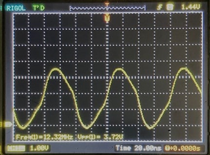
First of all, congrats on your new board. Here's the waveforms I'm getting on a ADAU1701MINIZ eval board:
MCLK1
OSC0
Microchip's MCUs of course also use crystals, so they have a few app notes which may help you with your oscillator:
http://ww1.microchip.com/downloads/en/appnotes/00849a.pdf
https://ww1.microchip.com/downloads/en/Appnotes/00002187A.pdf
Crystals can be temperamental. If all else fails, you could switch to a 12.288 MHz packaged oscillator where all the tricky stuff has been done.
Best regards,
Bob
Thank you, the oscillator appears to be working fine (needed the WP put to HIGH or it wouldn't self boot), I think it's my scope that is killing the MCLK due to the extra capacitance.
Please log in to reply.