ADAU1701 POP NOISE using SW Slew Rate
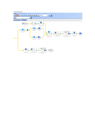
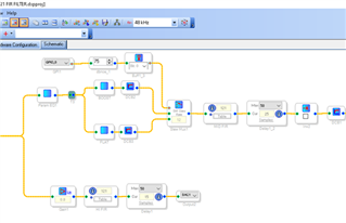
I am using an ADAU1701 in a board designed in the company, randomly I get a big pop noise when from the GPIO I select one 0 or 1 (see sigma studio attached), this selects one of two input signals. I have used DC Block based on other recommendations. The POP noise is still generated randomly.
even with no input signal we have the POP NOISE. Not using a microcontroller, just a simple switch to change 0 - 1, also in the code used a debounce of 100ms, should be enough.DOCX
Audio Signal Processors
SigmaDSP Audio Processors
adau1701
Hello Leithor,
I think you should place the DC block at the very start of the signal path. You are going through filters before the DC block so that could be amplifying the DC level.
Right now I do not see anything else that stands out to me but you only supplied a small picture of your system. You are using a slewed switch so that is good.
Zip up an send over your project. Simplify it if you want to keep what you are doing from being in the public. Just make sure the issue is still there when you do simplify the project.
Thanks,
Dave T
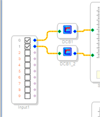
Thank you for the reply Dave, I added the DC block, problem is still there. Hope there is a simple solution.TITAN12 26 JUL 21 FIR FILTER.rar
Hello Leithor,
Thanks for sending your project.
I connected it up and had to make a couple of small changes. I had to change the switch to MP3 since I am using the MINI eval board. Also, the HF output I had to change to DAC3.
I added an oscillator on the input for testing. I set it for 80Hz which is where I saw you were boosting. I could press the switch and hear the change and not even a slight pop. Totally quiet!
So I hooked up my laptop audio out to it and listened to music and the switch is as silent as can be.
So I added some elements into the schematic since you had plenty of MIPS available. This may help you isolate what the issue is. I added meters at several places. You can clearly see the first DC block getting rid of the DC offset of the converters.
I added a meter on the switch output and one on the very end of the signal path. See if you can see these artifacts on the meters.
Check on your hardware to see if somehow GPIO6 output could be causing an issue? ( it is a stretch ) I do not know where else to look because I do not see any issues with your schematic flow. You can get rid of the other DC blocks, you only need the very first one.
I have attached my project but remember you have to make the few small changes.
Dave T
TITAN12 26 JUL 21 FIR FILTER-DT-Edits.zip
Thank you, you are correct, the switch was causing the problem. The program in sigma is ok.
Please log in to reply.