How to set EVAL-ADAU1466Z EVAL BOARD sample rate to 192Khz?
I have modified EVAL-ADAU1466Z EVAL BOARD to control AD1938 via Sigma Studio Version 4.6.
and set sample rate to 96Khz and got sinewave(40000Kz) succcesfully. When I had changed to 192Khz it did not working.
I'm able change register contents of AD1938 . ADAU1466 will be MASTER and AD1938 will be in slave mode. I want to change sample rate to 192Khz so, I expect to generate signals(sinewave with max frequency 80Khz). To do this I made following
configurations:
At ADAU1466 Side:
1-) I set System sample rate to 192KHz.
2-) CLOCK_CONTROL Tag START PULSE:Base_Fs*4(192Khz)
3-) MCLK OUT is set to 12.288 mHz.
4-) SERIAL_PORTS Tag:Serial_Outputs: Sampling Rate 4*FS , BCLK and LRCLK is MASTER
At AD1938 Side:
1-) PLL Control Register contains 0x80.
2-) DAC Control Register contains 0x04
3-) ADC Control Register contains 0x80
I wonder what's wrong with my configurations !
Audio Signal Processors
192khz
sample rate
ad1938
Integrated/Special Purpose A/D Converters
SigmaDSP Audio Processors
Audio CODECs
adau1466
Show More
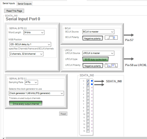
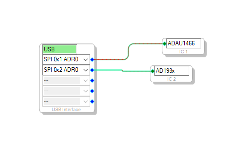
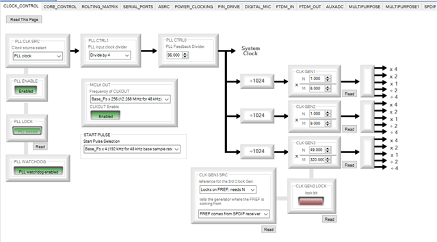
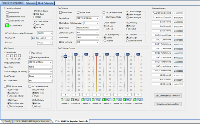
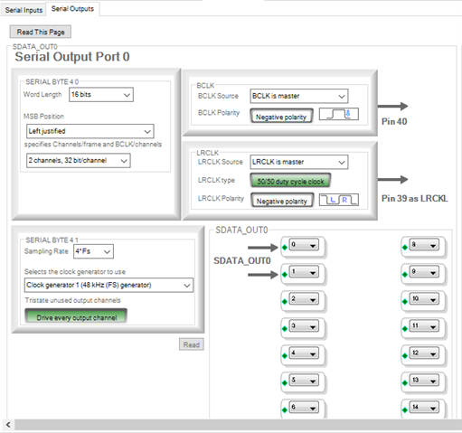
In addition to above settings ,when I set BLCK Active to Latch-End Cycle I ended up with pure 80Khz Sinewave at output.
Not sure if you addressed this in your modification but the Data Sheet for the Evaluation Board says that the analog outputs are optimized for 48kHz max.

Hello, I notice a number of mismatches in the configuration between the processor and CODEC.
DSP Serial Output Port 0 is set to Left Justified, but the AD1937 input is set to delay by 1 BCLK.
DSP Serial Output Port 0 is set to 16 bits/channel, but the AD1937 input is set to 24 bits/channel.
AD1937 ADC output is set to 16 bits/channel, but the DSP Serial Input Port is set to 32 bits/channel.
The ADC clock source is set to MCLK; I think this is the unfiltered input clock, and probably the PLL is a better choice.
It looks like you are using only 2 channels, so 512 BCLKs per frame does not seem correct.
I'd recommend the following for a standard application:
24 bit word length
64 BCLK per frame (32 bits/channel)
I2S format (BCLK delay by 1)
Let's start there.
Regards,
Josh
Hi Josh,
Thank you your attention , I had to update my settings not to confuse others.
I have following settings with CODEC(1938) and have 70 Khz Sine wave at outputs. Both ADC and DAC working fine.
PLL & Clock Setting:
Internal MCLK
DAC Clock Source> PLL Clock
ADC Clock Source> PLL Clock
ADC Controls:
Output Sample Rate> 192Khz
Word Width>24 Bits
SDATA Delay(BCLK Periods)>1
Serial Format>Stereo
BCLKs per Frame>64
BCLK Source> ABCLK Pin
BCLK Polarity>Drive Falling Edge
LRCLK Polarity> Left low
LRCLK Format> 50/50 Cycle
DAC Control:
Sample Rate>192Khz
BCLK Active Edge>Latch Mid-Cycle
LRCLK Polarity> Left low
BCLK Polarity>Normal
DAC Output Polarity> Normal
BCLK Source>DBCLK Pin
SDATA Delay>1
Serial Format>Stereo
Word Width>24 Bits
BCLKs per Frame>64
MCLK Pin Functionality>256*Fs
MCLK_O Pin>Off
PLL Input> MCLK
Kind Regards..
Please log in to reply.