How can I use a Multiplexer with a rotatory switch SP3T
Hi,
does anybody know how to interface a rotatory switch single-pole-triple-throw to GPIOs?, I need to switch 3 different paths A, B and C
I already saw how to do it using a toogle momentary switch but it doesn't fit my application, I need to use logic level to select the proper path
in advance thank you
Hi Ivan,
You can do that by using 2 GPIO pins. A logic level of 00 can mean path A , 01 - B , 11 - C
If the default path is A, otherwise you can choose 3 GPIO pins that will give you further flexibility.
Let me know if that answers your question
Thanks,
Akash
Hi Akash, thank you for your answer, maybe I didn’t explain myself clearly, the question is how to read the logic level of the GPIO’s in the program and how to use these data to make the proper path selection, if you can send
me a test program or example I will really appreciate it
In advance thank you
Ivan
I had a different way of doing this, in the ADAU1701 the audio path mux is controlled by a voltage level, so i used a resistor ladder to generate a voltage from the rotary switch and applied this to an aux_adc input, hope this helps
Hi Ivan,
If you are looking for an example on using the GPIO in input mode, and trying to understand it, there is an example in CCES Button_LED_GPIO.
This example reads the data from Pushbutton on GPIO and then toggles the LED's based on that.
You can also look at GPIO Programming Model in the GPIO Chapter in the Hardware Reference Manual.
Thanks,
Akash
Akash pointed you to the GPIO example code which shows how that part is handled.
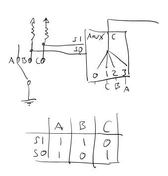
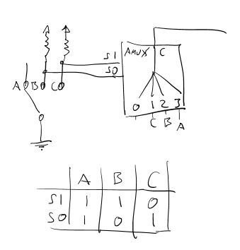
Regarding the hardware interface, if you always want the AMUX to follow the switch setting then you don't even need a processor. You can simply wire things up like this:
If the processor needs to know the selected channel but not change it conditioanlly then you could read signals S0 & S1. If you need to make a decision in your code about when to switch then you would read the two signals from the switch and drive the AMUX select lines from a second pair of GPIO pins.
Klaus
p.s. of course for a production circuit you would want to add ESD protection and all that jazz...
thank you Akash, where can I get the hardware reference manual for ADAU1701, also I tried to get the CCES Button_LED_GPIO example but I didn't find it
in advance thank you
Ivan
thank you for your answer, the hardware is understood, my question is relative to the software, I need to know how to read the GPIOs and then use the data to select the proper path in the schematic of the ADAU1701, I have read the AN-951, and in the several examples on it, the only missing example implementation of GPIO in software is the SINGLE-POLE SWITCH INPUT, which can solve my problem, if you have this implementation I really appreciate if you send it to me, in the other hand if you know where can I download the Hardware Reference Manual of the ADAU1701 would help me a lot
in advance thank you all
Ivan
I wonder why someone chose to remove my solution to this question because it works!!
Hi Ivan,
My apologies, I did not realize that this question was related to ADAU1701, and you are using Sigma Studio.
CCES and HRM are for other processors not the Sigma DSP processors. That is why you did not get the software example i mentioned.
There is a dedicated group for it. You can try to see if there is already a solution for this.
SigmaDSP Processors and SigmaStudio Development Tool
Thanks,
Akash
This question has been assumed as answered either offline via email or with a multi-part answer. This question has now been closed out. If you have an inquiry related to this topic please post a new question in the applicable product forum.
Thank you,
EZ Admin
Please log in to reply.