How to calculate the delay caused by an absolute value block?
Hello,
I would like to know how much is the delay (in therms of # of cycles) caused by an absolute value block.
Does SigmaStudio tool let us know this? I could not find any documentation where this is mentioned.
Thanks in advance!!
Hi KKSL,
Are you asking about how many cycles it takes ?. If it is, then it will be shown in the compiler output window.
Path : Left top corner >View > output.
There won't be any delay introduced/ caused by this block. This just gives a positive output for any input(positive/Negative).
Hope you get your answer. If not, Kindly revert us with a detailed question.
Regards,
Harish
Hello Harish,
Thank you for your early reply.
Yes, I wanted to know the # of cycles an absolute value block takes.
I am using ADAU1701 on SigmaStudio v4.6 and there is no compiler output.
So I created a new project using ADAU1467 and used an absolute value block. The compiler output showed that it takes 3 instruction cycles.
My question now is how do I delay a signal for multiple of 1 cycle e.g a No-Op library block in which we can input the # of cycles for which no-operation is performed on the signal at its input pin. The closest I could find is fractional delay.
Thanks!
Hello KKSL,
Let me jump in here for Harish,
The ADAU1701 was one of our early SigmaDSP parts and so the compiler output feature was not written into the code for it. However, there is some information available that can help to get the answers.
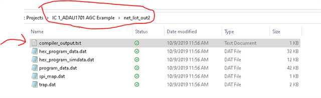
There is a compiler output file that is created when you compile the program. It resides here:
There is a folder called "IC 1_your-project-name" that has a folder called "net_list_out2". In that folder you will find the compiler output file.
Now it does not list out the blocks and the usage of each block, but it does output the MIPS and Memory usage of the entire program. So what I always do is take a project, compile it and look at the numbers. I write them down. Then I add in ( or subtract) the block in question and then compile it and look at the difference. This will give you how many MIPS are being used and how much memory.
For your other question. A No-Op will do you no good except waste an instruction. Because, the program is run in its entirety every sample period. So adding a No-Op will not delay the output by a sample period. You were close with the fractional Delay, you need to use the regular delay.
Here is where you find it.
Set the max to the largest you plan to use. Then set the "Cur" for the current setting you need. It is in samples.
Dave T

Hello KKSL,
I was thinking some more about what you said here:
KKSL said:
My question now is how do I delay a signal for multiple of 1 cycle e.g a No-Op library block in which we can input the # of cycles for which no-operation is performed on the signal at its input pin. The closest I could find is fractional delay.
First I want to clarify some terminology. When you say "Cycle" I am thinking of one instruction cycle of the DSP. There are 1024 cycles in this DSP for each sample period at 48kHz fs. So I think we are on the same page here when you say Cycle you are talking about one instruction cycle not one sample period.
The SigmaDSPs are stream processors that run the program during one sample period on the just received sample. Then it waits for the next sample period before running the program again. So waiting one instruction cycle does nothing in the program. There is no reason to wait one cycle or any multiple of a cycles. All it will do is possibly cause the program to not have enough cycles to finish the entire program during the current sample period.
The Fractional delay does interpolate between the two sample values to give you a value that is in-between sample periods. It is an estimated value.
Now every block in a schematic will not delay the signal processing in any way. So if you have one output that have a signal inversion block and one output that does not. There will be ZERO time difference of the output. Both outputs will be at the end of the sample period. This is because the entire schematic is calculated during the sample period.
Of course if you have filters or delay lines in one signal path and not the other there will be a delay between two outputs. A signal invert is just one multiply so no filters or anything that will delay the signal.
So what are you trying to do?
Dave T
Hello Dave,
Thank you for the explanation and excuse me for re-joining the thread after some delay.
The query is not for any on going project but to understand the technology, the process and the tool.
The signal inversion e.g. you gave above is not clear to me.
Let's take another example: I have a 2-way crossover. I want to boost the lo output by 3db and want the hi output to be as is. I then want to sum the two outputs.
I could do this by inserting a gain block with a value of 3db in the lo path of the crossover and the output of the gain block can go to an adder. The hi signal can go directly to the adder.
The other way would be to have a gain block in both lo and hi signal path with values 3db and 0db resp.
I think that the second method will be preferred? In the first method, The low path has a gain block that takes a few instruction cycles to execute its function but the signal will reach the adder only after one sample time where as in the second case both lo and hi signal samples will reach the adder at the same time with lo boosted by 3db and hi by 0db.
Thanks!
Hello KKSL,
No, you are missing an important detail. The entire program you see graphically is calculated every sample period. If you add a gain block on one signal path then add them up will all happen during the current sample period using the current sample as the data. There will not be any delay whatsoever unless of course it is an EQ that might have some phase shift or obviously a delay line. So your suggestion of using two blocks one for 3dB and one for 0dB is not the best way to do it. The 0dB gain block will only waste MIPS to multiply the current sample by "1". Both the Low and High outputs of the crossover will be ready at the end of the sample period even if one of them has some extra processing done. All the processing completes every sample period.
Look at an example of what you would do in an analog circuit to setup a differential output. You can take the output of an OpAmp and feed it to the positive output ( pin 2 of an XLR). Then take the same output and run it through another OpAmp to invert the signal and send that to pin 3 of the XLR. Some people do not like to do that because there is a small propagation delay and phase shift going through the inverting OpAmp. Well, in SigmaStudio you take an output and send it out through an inverting block it will not be delayed at all. Nothing. The positive output will be available at the end of the sample period and so will the inverted output. They were both calculated during the same sample period so no phase shift.
Dave T
Ah! I think I have got it now after I read through your example of op-amps.
Thank you so much, Dave!
Please log in to reply.