ADSP SC584 SHARC+: Enabling Link Port advances it's DMA's current address by 1 word and decreases current X count by 1
In our application we are using link ports to transfer data between an FPGA and the DSP at periodic intervals. We setup link port 1 (LP1) in DMA receive mode as prescribed in the HRM (pages 15-15, 15-16). After the data is received, LP1 and it's DMA are disabled so that they can be enabled in the ISR (see below) to handle the receive request (LRRQ) interrupt as shown below
// Step 1: clear LRRQ bit
ustat1 = dm(REG_LP1_STAT);
bit set ustat1 BITM_LP_STAT_LRRQ; // set LRRQ bit
dm(REG_LP1_STAT) = ustat1; // W1C LRRQ
// Step 2: enable Link Port DMA
ustat1 = dm(REG_DMA36_CFG); // LP1 DMA is DMA36 (see HRM 38-5)
bit set ustat1 BITM_DMA_CFG_EN; // set enable bit
dm(REG_DMA36_CFG) = ustat1; // enable LP1 DMA
// Step 3: enable Link Port
ustat1 = dm(REG_LP1_CTL);
bit set ustat1 BITM_LP_CTL_EN; // set enable bit
dm(REG_LP1_CTL) = ustat1; // enable LP1
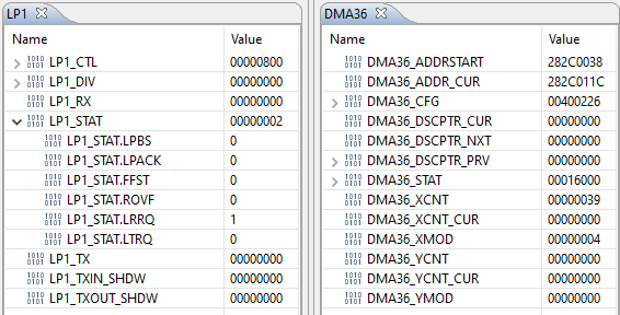
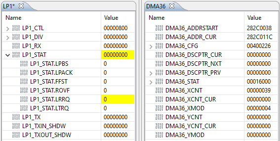
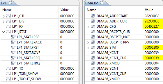
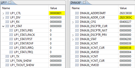
However, I'm running into issues where enabling the link port (Step 3) appears to advance the DMA start address and X count by 1 word. See the following snips of the LP1 and DMA36 regs.
On entry into the ISR
After Step 1: clear LRRQ bit
After Step 2: enable link port DMA (in Stop mode)
After Step 3: enable link port
note that ADDR_CUR has advanced by 4 bytes (1 word) and the XCNT_CUR decreased by 1
I haven't been able to figure out what's causing this and haven't come across any reference to this behavior in the HRM. I have tried using DMA in autobuffer mode and see the same behavior. Any information on what's going on will be very much appreciated.
Best regards
AG
Hi,
Please refer the attached code for ADSP-SC589 EZ-KIT which configures the link ports in DMA stop mode and transfers a buffer of size 1024 between the two link ports. After the transfer is completed the received data is compared against the transmitted one and a LED is toggled to indicate the Pass(LED11) or Fail(LED12) condition. Please take this as reference, which might be helpful for you.
attachments.zip
Regards,
Anand Selvaraj
Please log in to reply.