ADAU1463 index selectable demultiplexer
Hello everybody,
I have a quick question about the index selectable demultiplexer block:
Index Selectable DeMultiplexer [Analog Devices Wiki]
What signal is on the outputs, that are currently not selected?
In my prgram I want to trigger 8 value hold blocks subsequently. I have a 0 impulse ( one sample 0, all other samples 1) every 256 samples. Thus each value hold block should be triggered every 2048 samples.
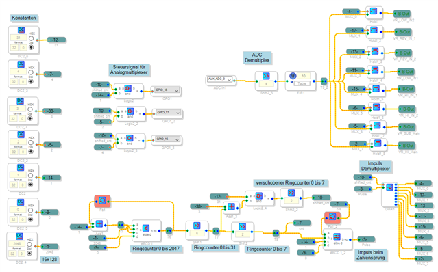
I want to use this to use a single AUX_ADC to read several potentiometers. Here is a screenshot from my program.
It works in general, but I have some wrong ADC readings every once in a while. Therefore I want to clarify whether the demultiplexer is a viable block for distributing the impulse. At the moment I am not sure, whether the value hold blocks are sometimes triggered unintenionally.
Best regards
Alex
Audio Signal Processors
software
adau1463
SigmaDSP Audio Processors
4.6
Hello Alex,
You are using an auxadc which uses 10-bit value as output and then you are shifting 4 bits to the right . So you can represent 64 different numbers with 6 bits. So you are probably exceeding the table values. You are giving out of range values to the table. If you shift that to 7 bits then we guess it would be fine. Try using the readback cells to read the value. The most useful thing in debugging is the Readback cell. You can read the values between any blocks . It shows the values of what currently runs in the DSP.
Kindly reply if the above thing is not clear to you.
Regards,
Harish
Hello Alex and Harish,
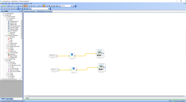
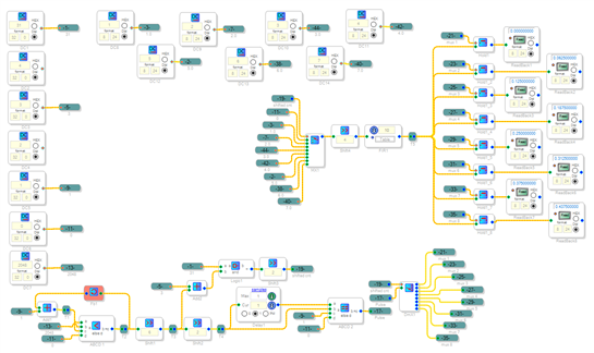
You've got a neat idea here! I built the project to see how it works on a ADAU1452 eval board (I believe this and the -1463 are code compatible). To simulate the external multiplexer hardware I used a Multiplexer block, as pictured below. The Hold outputs shown on the DSP Readbacks were as if painted on, suggesting that both the circuit's logic and the Demultiplexer are working as expected. Thus there may be an issue with the signal coming in from the Aux ADC.
AST said:
I have some wrong ADC readings every once in a while.
How large are the errors when they occur, and how often? Did the FIR Filter help? If the errors are relatively small, you could try LP filtering each Hold output individually. If on the other hand it appears you're getting bleed-through among neighboring pot channels, perhaps the timing (your shifted count) needs adjustment. You could temporarily bring out some of the timing-related signals to spare DACs on your board, for viewing with a scope.
Best regards,
Bob
Hi once more,
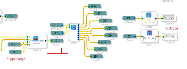
It may work better if you flip the polarity of the Pulse signal so it's high only at the desired moment of Hold block update. Either way works on my example with its artificial signals, yet I suspect having the Pulse go high when the Aux ADC is stable will work more reliably for you.
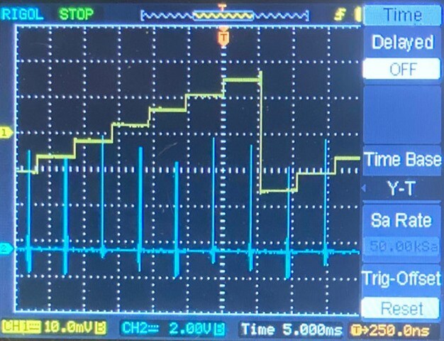
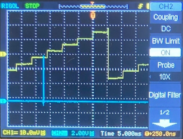
I took my own advice and scoped the timing signals -- these are with the modified logic:
Above: Shifted count and Pulse -- note that the audio DACS aren't designed to handle control signals, yet they show that the timing appears reasonable for this design.
.
Shifted count and MUX4 -- showing that the DeMux correctly distributes the pulse.
Best regards,
Bob
Dear Bob,
I checked the clock signals for the multiplexer and and the read impulse on a scope. Everything is as expected.
I also put the read impulse on an additional GPIO. It occurs after three quarters.
I also checked the analog signals with a scope. It looks fine, but the scope has only 8Bit, so I might miss signal distortions.
I will definetly check out what happens if I invert the impulse logic.
Best regards
Alex
Hello Harish,
thanks for your answer. I am not sure if I understand what you mean by exeeding table values. I only need 6 bit accuracy. I provide them directly to a look up table with 64 values, or at least this is the plan. If I use the Look up table directly with an ADC it works flawlessly. We are using this technique for many years now and we never had any issues.
Best regards
Alex
Hello Alex,
I had quickly looked at your project and missed some details. I had asked Harish to respond with my thoughts and he did. I looked at your screenshot a little bit closer. By the way, it is usually much more helpful to include the project file. Saves us time and we can be more detailed in our response. Anyhow, Now I see that you did correctly send the mux control the values of 0 to 7 in integer format. So the overrun of the index is not the problem.
So at first I thought that you may be switching too quickly but 256 x (1/48K) = 5.3ms. So that is plenty of time for the new DC value to settle. What I cannot tell is the timing of your pulse with respect to the MUX enable for each channel. A channel being one of the 8 pots. What I think may be happening is that you are sampling when the new value has not settled. The best test is to alternate the pots between MAX CW and MAX CCW. So this means the ADC value will go from max to min every time it switches. See what values you come up with. Use Readbacks to look at it. Then set all of them at min and see that the values are and then all at max and see what the values are. Then compare those numbers to what you got when they are alternated. They should be the same if there is enough time to settle to the new value.
I will attach a project that is a bit complex but what it does is delay the hold latch until shortly after it changes channels and then goes low shortly before it changes to the next channel. This keeps the latch signal from the mux clock edges. This should ensure no crosstalk between channels.
This project is for the ADAU1701 but you can find the same blocks in the 1463.
See if this works better for you. The square wave generator frequency of 100Hz will be pretty much exactly what you are doing now for scan speed.
ADAU1701 AUXADC External MUX Example 8 to 1.dspproj
Then one other thing. The FIR filter. This will add settling time to the switching between channels. It is only a 10 coefficient filter but it will add to the time. The FIR filter is what confused me earlier. I thought it was a table you were using of ten values until I could see the small text under it that said "FIR". So it looked like you were feeding 32 values to a ten value table.
So you are shifting the 10 bit value over by four bits. This is dividing it by 16. I do not think you need a filter at all because you are truncating four bits that would be most of the noise content of the signal. In the 1701 we have a four bit hysteresis filter which gives you about the same result. So I would try to get rid of the FIR filter and see how that works.
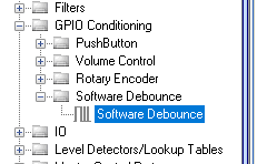
Then you can also try the debounce block if the value is still bouncing around too much.
Just do not set it to be too long.
Enough for now.
Thanks,
Dave T
Hello Alex,
Harish was repeating what I suggested to him. I responded on Jun 3rd to explain more.
Dave T
Hello Alex,
I just had another thought on your issue. How do you have the pot connected in hardware to the AUXADC input pin? Is it a long wire to the pot? My reason for asking is that the ADCs are SAC type and there are no antialiasing filters. I wonder if there could be some transient interference like an RF signal or other signal on the board that could cause the reading to wildly change? Do you have a small RC filter on the output of the pot near the pin?
Just a thought that the issue may have nothing to do with software running in the DSP. Could be an external source.
Dave T
Inverting the logic did the trick. I misunderstood the help of the hold block. I thougt the inverting logic was needed, but it turns out it works perfect with the normal logic.
With the inverted logic there was an unwanted trigger for the hold block in the worst possible moment directly when the analog switch is active. Thanks for the support everybody.
Thanks for this information Dave. I will keep that in mind. The hardware is not ideal, but it is sufficient since we need only 6 bits.
Please log in to reply.