adaptive filters
Hi,
i am working on EVAL-ADAU1467Z evaluation board. I am working of filters. is there any documentation available on adaptive filters and their use in sigma studio.
Thank you
Hi harishsharma,
I hope you have gone through the wiki page for adaptive filters, It has the basic view and control over the block and its functioning. There are few posts on the forum regarding adaptive filters where our experts discussed and you can find it by searching in the forum. Here are the few posts where adaptive filters are used by customers for their application. If you want anything in specific then feel free to post a question.
Using an NLMS filter for background tones/beeps - Q&A - SigmaDSP Processors and SigmaStudio Development Tool - EngineerZone (analog.com)
Help with Modified FxLMS/FxNLMS in an ANC application - Q&A - SigmaDSP Processors and SigmaStudio Development Tool - EngineerZone (analog.com)
Regards,
Harish
Hello Harishgowtham,
i have already gone through wiki page. i am trying to extract a tone from mixed tone signal.
tone_extract.dspproj
at the filtered output i think i am getting desired signal. but not getting anything at error signal. if i decrease the value of alpha to 0.00001 then i am getting tone at error signal. i don't know the way i am following to extract a tone from mixed frequency tones is right or not.
Hello harishsharma,
You are not supposed to get anything at the error signal. That is the way it works. The alpha is an adaptation rate that is the rate at which it adapts the step size. If you keep on decreasing that it doesn't converge. So it's not gonna do what it is supposed to .
The alpha is so small , so its not adapting so that you are getting a tone in the error signal.
Regards,
Harish
Hello Harishgowtham,
with NLMS filter we can extract desired signal frequency from mixed frequency signal. i am trying to do feed forward ANC. we need to generate 180 degree out of phase noise signal. if i feed directly by inverting the signal to speaker that does not give that much good ANC effect. i think that is because of we don't know exact amplitude of noise. can i use NLMS filter to do it. in this case input signal is not mixed frequency signal.
Thank you
Hello Harishgowtham,
i am trying to do Active Noise Cancellation using FxLMS filter. i connected two pdm mic. one is for error signal and other is for noise signal.ANC.dspproj
i have a doubt regarding filtered reference signal. i don't know i am following right way. i am feeding white noise at filtered reference signal. is secondary path internal there in FxLMS filter. what i did i connected err mic inside the cup of headphone and other mic outside the headphone.
Thank you
Hello,
What is your expected output? If you want to remove 120 from the mix of 120 + 600 then you need to swap the FIR in and Desired in signals as shown below. The output is the NLMS error output. See the plot below, the 120 has been removed from the mix.
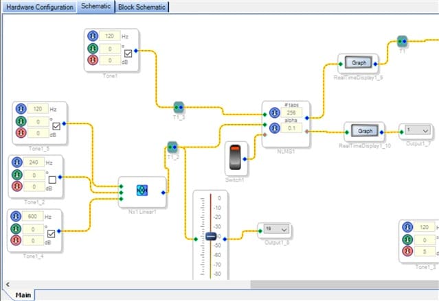
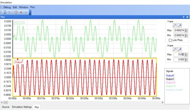
Hello bitmechanic,
expected output was 120Hz at filtered output pin. so i connected 120Hz at desired signal pin. mixed frequency at pin0(input to FIR).
you connected 120Hz at input to FIR and mixed frequency at desired signal pin. how you drawn that plot . in my system i can not draw frequency more than 5 Hz.
Thank you
Hello,
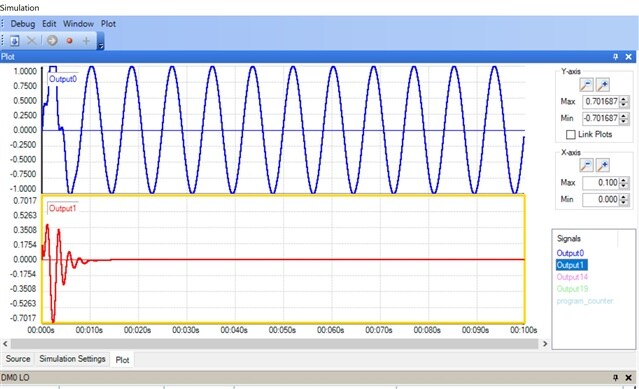
Ok I see. I go back to your original schematic. The NLMS FIR out will be 120, and the error will go to zero as shown in the plot below.
Please log in to reply.