How to simulate Slew Rate for Waveshaping
one thing that I curious about,,, could we simulate "slew rate" for waveshaping?
Edit Notes
The topic of this post did not match the topic of the old thread it was posted on. I split off this post and gave it a new name.
[edited by: DaveThib at 4:42 PM (GMT -4) on 1 Sep 2022]
Choose a category
Hello Julius,
I need a lot more information to be able to help you. Your post is FAR too general and devoid of details.
What DSP?
What revision of SigmaStudio are you using?
What sort of waveshaping are you trying to do?
The term "simulate slew rate" I do not understand what you mean?
Please explain what you are trying to do.
Dave T
Yes Dave,
I'm sorry, I missed your reply, there's no notification aside from my last thread. I didn't know that you replied me.
- Adau1452
- SigmaStudio 3.6
- Slew rate waveshaping that I meant was the emulation of signal that went through electronic network ( my example is opamp preamplifier with clipping distortion).
The process causing the signal distorted in such way that affect to sound produced by the circuit.
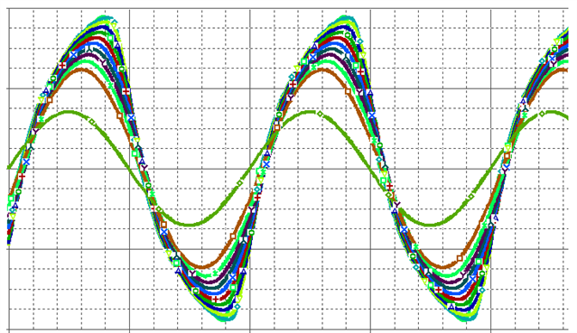
I only know by learning it visually on how the signal behave. when I sent sinusoidal into the preamp circuit, the signal that comes out is kind of 'leaning forward'. that happen when the gain set high on the amp setting. kind of look like this:
The clipping distortion in sigmadsp is 'too perfect'.
Seems like something is missing. but then again that was probably what my ears want to believe.
and here we go again chasing the 'old' taste.
I am not sure if I explain it clearly.
Hello Julius,
Thanks for the extra details. You can go into the settings on EngineerZone and set the notifications to notify you of answers to your posts or other replies on posts you are involved in. It has been a while since I set that up but there are some settings for this.
So is this screenshot from a tube amplifier? It reminds me of the distortion you see when you are driving a tube amp hard and the power supply starts to sag on loud notes. This distortion/compression is what makes those amps sound so good. I have heard of people trying to emulate this in other analog circuitry by putting a higher impedance in series with the power supply. Optimally, something that is also not linear like a light bulb. It will have low resistance when cold but a lot higher as it warms up. So it will change with signal level. I do not think anyone has come up with a great circuit that sounds anywhere near as good as a good old guitar tube amp with the weak power supplies. The tubes also sound better as they age and get more gassy ( glow blue) for the same reasons, it limits the current through the tube.
In the digital domain, this has been going on for a long time, people will sample the transfer functions of a piece of equipment and then develop a differential equation to implement in a DSP. This is out of my expertise in how to do that. I suppose it should be possible to do this within SigmaStudio but it would take a different way of doing it.
The best way to see if this is possible is to find an equation that describes this distortion, then see if it could be implemented in SigmaSudio. Really interesting question but I not have an answer. Hopefully, others on the forum might have some ideas.
Dave T
Hi Dave.
the picture was from 'tube screamer pedal' ( already covered in another thread on this forum) . I was going to link you into the site that provide those picture but at the point I wrote that the site is down so I can only send you a picture.
I simulate everything that I could find ( and understand) on google but . .yeah, I failed.
for example, Hilbert Transform, in which (in my understanding) transform a signal into 2 separate signal in 90 degree phase.
yes they are valid, but, only for sine wave, for actual audio, and clipped audio, nah, they're destroyed.
and there's no trigonometry on adau1452, so I cannot experiment on that.
I still lack knowledge.
Julius.
Hello,
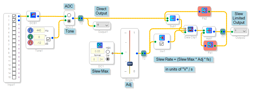
Here's a simple slew rate limiter:
The heart of this circuit is the adder with feedback to itself, which holds its output from one sample to the next. If the adder's other input is zero, the output remains constant. The present output is subtracted from the input, resulting in an error signal which when fed to that adder, corrects its output to the input's new value each sample. But this error signal is limited by the DC Source, Volume Control (used as a DC pot) and Data-Controlled Clip block so that output slewing is allowed only up to the rate set by these blocks.
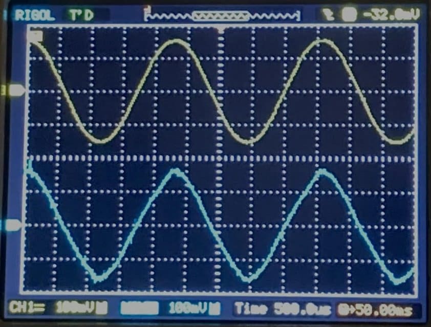
With the sine wave input, here's an example with the slew rate just insufficient to allow the fully undistorted sine wave to pass:
The slew limit slows the rise and fall of the sine wave, at the expense of its top and bottom. Reducing the slew rate turns the output into a triangle wave, then progressively cuts its level until at zero slew, it disappears (the output can never change). This effect is easily heard over headphones. As you reduce the slew rate with a music input, first you lose the high-end definition, then distortion increases until it sounds like an old transistor radio. Hopefully, this is the desired effect when used with a single instrument (e.g., guitar) as intended.
Since the slew rate is set by a DC level, you can easily make this user-adjustable or even automatic, as desired. Modify as desired, that's where the fun is.
Best regards,
Bob
1452_SlewRateLimiter2.dspproj
Hi Bob,
Thank you for the example. I'll try this and report the result soon.
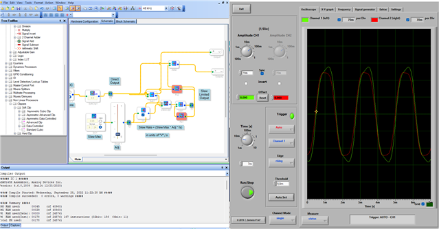
it works on clipping!
thanks Bob, i'll use this setting.
Best regards.
Julius.
Please log in to reply.