MCLKI current draw when PVDD/AVDD off (ADAU1701)
I noticed an oddity with this device. For my design, I have to turn off AVDD/PVDD in standby due to a power-hungry codec elsewhere. This keeps us in compliance with standby current.
Trouble is, with PVDD off (basically grounded) the MCLKI pin seems to be drawing enough current (~15mA) to drag down my master clock oscillator. (Standalone, not a crystal circuit). This brings the clock amplitude too low to drive the microcontroller at the heart of the system. A problem! This current draw doesn't seem to be described anywhere in the datasheet, but it's an edge case.
This is cured by placing a resistor in series with the clock, limiting current, but kind of sacrifices the quality of the clock signal. I'm not crazy about doing this.
So I'd like to power PVDD from the 3.3V digital supply (IOVDD), not analog as usually recommended, as it's always on. But this PVDD also powers the aux adc, correct? So this might create a little noise in my aux adc?
Then what does AVDD power, the audio ADC's only? (This isn't mentioned in the datasheet either).
Edit Notes
more info
[edited by: joe42 at 5:00 PM (GMT -5) on 1 Feb 2023]
Audio Signal Processors
hardware
mclk
SigmaDSP Audio Processors
adau1701
Hello Joe42,
There is nothing wrong with the MCLKIN pin. This is what is happening.
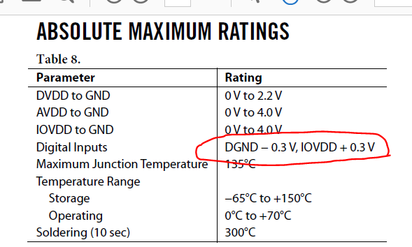
Look at the absolute maximum specifications:
Digital inputs are bounded by 0.3V above IOVDD and below GND.
If you shut off the IOVDD this value becomes 0V so +0.3V violates the max input voltage. what is happening is that the ESD diodes/circuits, are forward biasing and trying to power the entire part via the master clock input signal! I have found on the bench on some of our smaller low powered devices that I can keep the part running after shutting off the power by keeping the clocks from the test equipment turned on. The part keeps working even when the power is off!! So I have to be certain to shut off all clocks.
By the way, the same goes for the AUX ADC inputs. If those are still connected to power it will also violate the max input.
the solution is to use a level translator. You tie the input power domain to your system power and the output power domain to the gated power to the DSP. So when you gate the power to the DSP the level translator power goes to zero and it shuts off the drive and isolates the clock from being loaded down.
You need to do this everywhere you have power like the AUXADC inputs or other GPIO inputs. If they remain on the "always on" power domain then you need to use level translators or analog switches to shut off the feeds to the DSP.
You are correct that the AVDD is pretty much only for the AUXADC section and the PVDD is for the analog portion of the PLL. Part of the PLL is an analog VCO. You really need to keep the PVDD power as clean as possible to avoid PLL locking or unlocking issues. If you want to run it off of the digital supply then at a minimum you need to use a ferrite bead and so additional bypass caps to keep the PVDD clean from noise. It is not the recommended thing to do but you may be able to get away with it. PCB layout will also be important.
Dave T
Thanks for the reply! Sorry if I wasn't clear but IOVDD is always on. What I'm turning off is PVDD/AVDD. So I am not violating that condition. Been a while since I made *that* mistake!
When PVDD is turned off MCLKI draws a surprisingly high amount of current, that wrecks my clock.
I can see why I'd want to keep PVDD clean by using a clean source like the ADC uses.
The datasheet says that PVDD powers the PLL as well as AUXADC, which surprises me (p.13,45) but I'm sure there are reasons. The datasheet doesn't say what AVDD is for (as far as I can find) but I'd imagine audio ADC.
Not sure my solution here; ultimately the whole purpose is to reduce standby current to pass the requirement, and to do that I need to turn off the regulator feeding PVDD and AVDD of both this chip and a codec. I don't really want to add another regulator just for PVDD, and I don't like the idea of using IOVDD as you mention, or this series resistor hack.
Hello Joe,
Well, it seems to me you have proven that the MCLKI is powered off of the PVDD so you cannot turn it off while supplying a clock to the pin. The solution that is not a hack is to use the level shifter I mentioned.
I cannot ask any designers about these details anymore because this part was designed so long ago.
I am glad you understand the IOVDD being powered down issue. Not that many people realize this until they come across it. So thumbs up on your skills.
Dave T
Got it. I think I can get a level shifter or similar to drive MCLKI. Since it's unidirectional maybe just a FET or something would work. I think I have a few on the BOM already.
Oh believe me, I learned about the IOVDD thing the hard way long ago. I had forgotten about my I2C lines being active..
Please log in to reply.