Problem while flashing the ADAU1452 through I2C
Dear Sir or Madam,
I'm currently trying to use the ADAU1452. My purpose is to flash a program into the ADAU1452 in I2C using a MCU. I've validate that it was possible with the eval board (I'm able to make a Led blink). I'd like to do the same with an ADAU1452 (package KCPZ) on my own board. I'm sure that the component is able to communicate in I2C. When I write the program data in it and read the registers back, the values are the good one. But when I do the all Sequence it doesn't work.
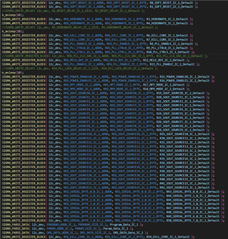
If I comment the line where the clk source is configured and I dump the I2C values they are stored into the chip but when I uncomment this line I can only read 0s in the same registers
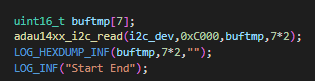
Please find an example of what I dumped :
without the line commented :
With the line commented :
Do you have any idea what could be the problem ?
Have a nice day,
William.
Audio Signal Processors
adau1452
adau1467
SigmaDSP Audio Processors


Hello William,
Did you successfully boot the DSP from your controller? You booted your DSP and reading a random register gives you a wrong value?
WillSafehear said:
But when I do the all Sequence it doesn't work.
A booting from a uC needs this sequence to be written to the DSP. Commenting a control register would be problem unless its default value is what it is supposed to be in our config. But that is not the case with the PLL_CLK_SRC, its default value is 0 but we need that to be set as 1 to have max system clock. So, something strange is happening in I2C commands to the DSP, if the DSP boots by commenting those clock sources.
WillSafehear said:
If I comment the line where the clk source is configured
Did you mention the PLL_CLK_SRC and three delay functions that you commented in the above code?
WillSafehear said:
I've validate that it was possible with the eval board (I'm able to make a Led blink). I'd like to do the same with an ADAU1452 (package KCPZ) on my own board
Did this LED blinking program work in your board? it's working and reading any registers gives you an unexpected value? If it is, then there may be a programable error with the reading function.
The code snippet that you dump is a function for reading the registers in the DSP right, have you checked that this function works fine and reading proper values previously? otherwise there may be a problem with the code of reading the register.
WillSafehear said:
With the line commented :
Is this an expected value from a register that you had read?
Probe the signals and see if the I2C commands are correct.
Make sure that you don't have any signal integrity issues. Have you had a decent clock and data signals?
You have connected the pull up resistors to the circuit, right?
If you successfully booted the DSP, then read/write a DC value from your program and verify the I2C commands in the scope.
Kindly clarify the above things then we will proceed further.
Regards,
Harish
Hi Harish, thanks for the feedback.
To explain a little bit more the objective of my board is to compare audio and consumption performances between ADAU1467 and ADAU1452 (due to component crisis) .
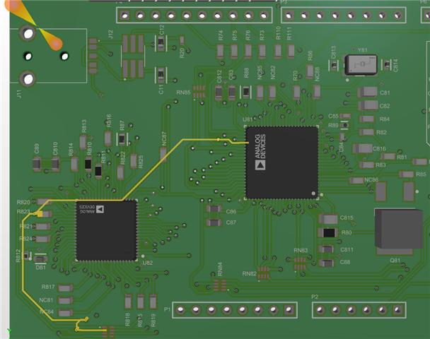
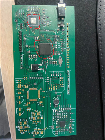
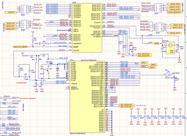
I've then made the following shield :
And on this shield I choose to solde one of the two DSP. I checked that I could correctly boot (in I2C) the ADAU1467 by making a Led blink or by communicating in I2S with a codec. My alimentations 3.3V and 1.2V are correct, the oscillator signal too.
But when I use the ADAU1452 instead (by removing the ADAU1467 and solder the ADAU1452) the alims are still correct, the oscillator too. I can talk with the Adau1452 in I2C but it seems like I can't achieve a complete boot.
I'll try to take more pictures of the signal but while I do this I'm open to any idea.
Have a nice day,
William.
Hello William,
It seems to be a hardware issue. are you sure about the I2C addressing?
Are these two processors connected in the same I2C bus with same address?
WillSafehear said:
But when I use the ADAU1452 instead (by removing the ADAU1467 and solder the ADAU1452)
The pin packages of these processors are different, are you removing the ADAU1467 and soldering the ADAU1452 in the same place?
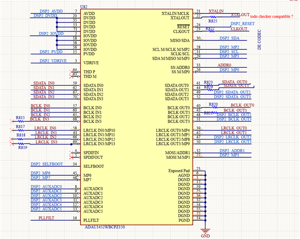
It's quite tough to read the line that you have drawn in the schematic. can you share your full schematic?
Make sure that the chip address where you are writing to is correctly set. The uC code template that you use may be correct since you have booted the ADAU1467 successfully, but you have to adjust the code for addressing and few things to work with the other chip. please verify that those are correctly given.
Regards,
Hi Harish,
I don't think I have I2C issues because I can modify different register.
I don't solder the ADAU1452 in the same place. There's two different places on my board, I always leave one of them empty and solder the DSP I want in the right place.
To boot the DSP I use two differents code templates (one for the ADAU1467 and one for the ADAU1452).
I'm able to boot in I2C the ADAU1467 when I solder it on my board
But I'm not able to boot the ADAU1452, even if I've validate the template for the ADAU1452 by booting Analog devices ADAU1452 eval board in I2C with my uC.
Please find my schematic below:
Have a nice day,
William
Please log in to reply.