ADAU1701, Initial state of GPIO, controlling MUTE on DRV632
Hi Forum
I'm working on a ADAU1701 board, where I'm using DRV632 buffers as output filter from the DACs to ensure pop free startup from single supply.
DRV632 has a Mute pin (pin 5) which is active low.
I'd like the Mute Pin to be low until everything is setup correctly in the ADAU1701.
Therefore I'd like to use one of the GPIO pins on the ADAU1701 to control the Mute function.
For this to work the initial state needs to be low.
If I configure the ADAU1701 pin as digital output, will it then be low at startup and stay low until I in the SigmaStudio program lets it get high (using a predefined delay)??
Thanks in advance
Audio Signal Processors
hardware
mute
SigmaDSP Audio Processors
gpio
adau1701
Show More
Hello MadsM,
What hardware are you using?
The tricky thing here is that the GPIO pins are always setup out of reset to be an input. As such it will float high if allowed to by the external circuitry. Then the DSP program needs to load up and then make the pin an output, or make it an actual GPIO pin depending on which pin you are using. So this takes time.
I have run into this with other designs so I either try to avoid active low situations or I use a pre-biased transistor to invert the logic externally. So this way when it powers up the collector will be low because the transistor is on. Then setup the DSP program to give you a low out after a timeout.
I can provide a schematic of this, there are examples on the forum but might be tough to find. Can you let me know what hardware you are using and if ti is your own then post a screenshot of the GPIO pin schematic and which pin you are using? We may be able to work around this with hardware.
Dave T
Hi Dave
Thanks for answer.
Hardware is (or will be) my own.
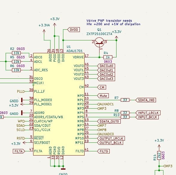
Yes I have used Pin 11 / MP0 for Mute output, and has planned on using a inverting transistor to drive the mute on the DRV632s (mute active low).
I have used the same before with ADAU1701 and PCM5102A, using Pin 28 / MP3. I works fine on that, but I was wondering if I was just lucky with some of the timings and the internal UVP circuit in the DAC, and want to be able to predict the outcome a bit better.
Thanks ;)
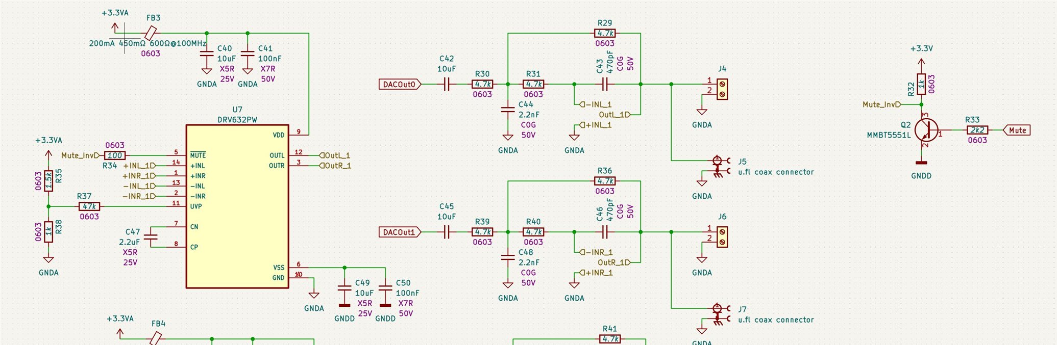
Hello MadsM,
Thanks for the details.
As I mentioned earlier, the MP pin will power up as an input so it will want to float up to a high due to leakage. Adding a pull-down resistor will solve that issue so I suggest you can add around a 47K resistor to ground should be enough to ensure that the pin will remain low until it is initialized by loading the DSP registers and program and then the program will set the pin state.
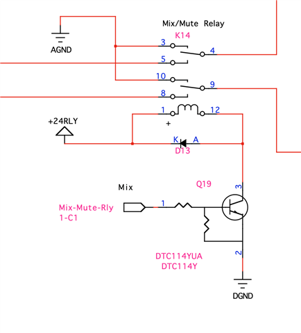
Here is a schematic from a personal tinkering project I have done using a pre-biased transistor. I really like these because it saves several parts so less cost and space on the board. Here is how I used it to drive a relay but it can easily be used with one external resistor on the collector up to the power like you are using. This part has around 57k to ground from the base pin. I use it with a PIC uC and it works well.
I drew the internal resistors in the symbol for my reference but they are internal to the part. You can see the pin numbers on the edge of the symbol.
The resistors are a 10K in series and a 47K to ground.
Dave T
Sorry for the late answer on my part .... but thanks a lot. I'll for sure include a pull down resistor in the coming design. Thanks and KR Mads
Please log in to reply.