ADAU1452 and PCM1802, Problems writing SPI EEPROM and no signal from ADC
Developing a ADAU1452 based board, using PCM1802 ADCs and PCM5102A DACs
Have the board up and running.
All PSU voltages within spec
I can program it through I2C via Wondom ICP3
I can flip an GPIO pin and light a LED
MCLK 24.5MHz
BLCK 3 MHz
LRCLK 48 kHz
Also got the DACs to output signal generated with the sine block in DSP
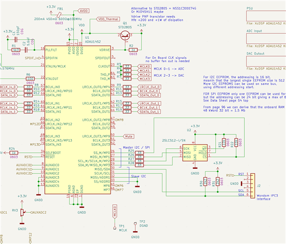
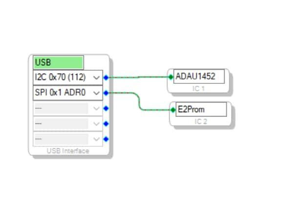
I'm using the I2C interface for programming and the EEPROM (25LC512-I/SN) is connected to the Master SPI port (MP0-MP3)
When trying to write to the EEPROM, there is no signal on the port, but signaling on the port used for I2C !!!! How do I tell the DSP which port to use for the EEPROM??
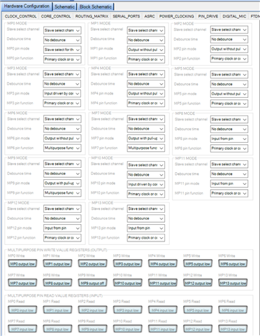
Second problem is the ADCs. I think I have connected these correctly (please se schematics below) and I'm outputting MCLK, BLCK and LRCLK as stated above. Data line is just Zero. I would have thought that the PCM1802 would just output data with this setup. DAC put in Slave Mode. What am I doing wrong. See registers.
Thanks a lot for any hints and help on this.
adau1452
adc
hardware
eeprom
sigmaStudio 4.7
slave mode
Show More
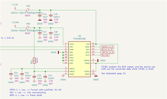
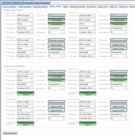
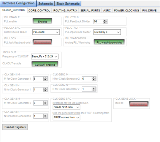
Ok, I think I solved the ADC issue. Just realized that PCM1802 needs a 5V psu for the analog part ..... I'm only giving it 3.3V!
Giving PCM1802 5V on the analog psu made the difference, and now it is outputting data. Damn, why didn't I realize this in the design phase.
The EEPROM issue still persist ... help needed ;)
Ahhhhggggg .... Not sure what I have been thinking, but even stating here that I am using a 25LC512-I/SN EEPROM, I was still thinking about a 1Mbit size!!! .... corrected the settings for a 512kbit, 128 byte page size with 2 address bits, and it all works.
The thing about signals on the bus not being visible, was due to it's burst nature, and the scope not being set well enough, so didn´t see it
But now it boots as is should

Hello MadsM,
Awesome! Glad you found the problem. Yes, it can be tough to capture the SPI and I2C signals. What I do is set the scope to single sweep and set it to trigger off of the SS line or the SCL and I can usually capture it that way. It takes a few tries to get the trigger level and horizontal sweep rate right but then you can see the comms.
Dave T
Please log in to reply.