ADAU1701 newbie questions on hardware implementation
Hi all,
I am planning the use of the ADAU17x in a new hardware design. I have a few questions after going through the data sheet several time.
Q1, We will be controlling DSP through I2C with our MCU for some general tasks but will be loading most configuration through Eprom in Self boot mode.
I am trying to work out how to use I2C control from our MCU whilst keeping boot mode as most schematics show one or the other.
My understanding is :-
SELF_BOOT = HIGH
WP = HIGH (but for initial programming LOW) or program eprom out of circuit
WB = this is what i am unsure about, i did read WB needs to be disabled so that ADAU17 is not acting as I2C Controller/initiator, so i am guessing pulled to Ground????
Note: Our MCU is 5V so we will need to employ level shifting, though some users seem to report this is not needed if supply voltage on both devices is within tolerance??
Q2. RESET
From my understanding this is a Power up delay to allow DSP to stablise and Initialise Properly. On many schematics i have just seen this pulled to 3.3V via 10K resistor.
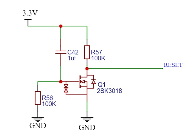
I had though of another way, as shown which may ensure enough of a delay as shown in schematic, or is there another preffered way (Not MCU controlled)??
3. Unused IC Pins, can be left floating or better tied to GND / resistor-GND ??
Thanks
Marty
Audio Signal Processors
hardware
SigmaDSP Audio Processors
adau1701 micro controller
adau1701
Hello Marty,
It is usually good to work on developing your program with the selfboot disabled. (low). This way the DSP will not try to selfboot every time SigmaStudio sends a soft reset.
Once the program is developed and you program the EEPROM. Then you can rise the selfboot pin and boot up from the EEPROM. Once it is booted you can still communicate with the DSP. You just have to wait for selfboot to complete before trying to communicate with it. This also applies to SigmaStudio not just your host processor. you can have the part selfboot then as long as you have the EXACT same program loaded into SigmaStudio, you can click on "Link/Compile/Connect" and SigmaStudio will compile the program so it knows the addresses of the objects but will not download the program. It just enables the communications link so you can move GUIU objects and read meters etc. Just like your host controller will do.
WB is WriteBack. This is for the feature where you can write back eight settings using the interface write blocks, back to the EEPROM when power is going down. It can also be setup for multiple writes but it is not simple to do. There is a post on the forum where I explained all of this. So the WB pin is how you trigger this. Then once triggered the DSP will lower the WP pin to remove the Write Protect off of the EEPROM so it can write to it. This also means that the DSP comms port is now a master port again so the host controller should not be writing. usually, any designs that have a host controller do not need to use this function. It will be done by the host controller.
The WB pin you set according to the I2C address you want to use. It is a multi-function pin.
The WP pin you can pull up to IOVDD. You do not have to connect it to the WP pin of the EEPROM if you are not using the writeback function.
You WILL need to use level shifters. Or find a 3.3V controller.
I like the delay of the reset line. I always seem to think it is more reliable for startup that way. Not that I have seen a problem on this part but I have seen it on another part. you could use a simpler circuit like a 10K pull up and a cap to ground. Your circuit looks like it would give a decent delay and a smooth transition up to voltage.
Unused pins.... Kind of depends on which ones. The DAC outputs can be left floating. The ADC inputs I would ground through a resistor and cap. That is the safest. Digital pins if they are MP pins I would set them to be GPIO inputs and then ground them.
Dave T
Again Dave many many thanks for taking the time to provide such a detailed response which will help a lot in our prototyping. Thank you
Please log in to reply.